Reflective optical element, optical system and EUV lithography device

a technology of optical elements and lithography, applied in the field of reflective optical elements, optical systems and euv lithography devices, can solve the problems of degradation or contamination, inability to achieve desired imaging, and inability to achieve imaging errors and transmission losses, etc., to achieve less effect, high reflectivity, and lower intensities

Inactive Publication Date: 2006-04-13
CARL ZEISS SMT GMBH
View PDF6 Cites 22 Cited by
  • Summary
  • Abstract
  • Description
  • Claims
  • Application Information

AI Technical Summary

Benefits of technology

[0032] Reflective optical elements at the end of the wave path, which are used for the actual imaging, are narrow-band and only subject to a slight radiation intensity. These should be optimized for a high reflectivity. For because of the overall lower intensities, the emission of photoelectrons should have less effect and result in relatively less contamination.
[0033] A special advantage is that one can adjust an approximately identical lifetime for individual grou

Problems solved by technology

This generally leads to a degradation or contamination, e.g., by oxidation, carbon deposits, interdiffusion, material ablation, etc., of the multilayer surface.
These effects lead to imaging errors and transmission losses.
In the worst case, the desired imaging is totally impossible.
Thus, regeneration cycles must be provided during operation of the EUV lithography machine, which not only significantly increase the operating costs, but a

Method used


Image

  • Reflective optical element, optical system and EUV lithography device
  • Reflective optical element, optical system and EUV lithography device
  • Reflective optical element, optical system and EUV lithography device

Examples


Embodiment Construction

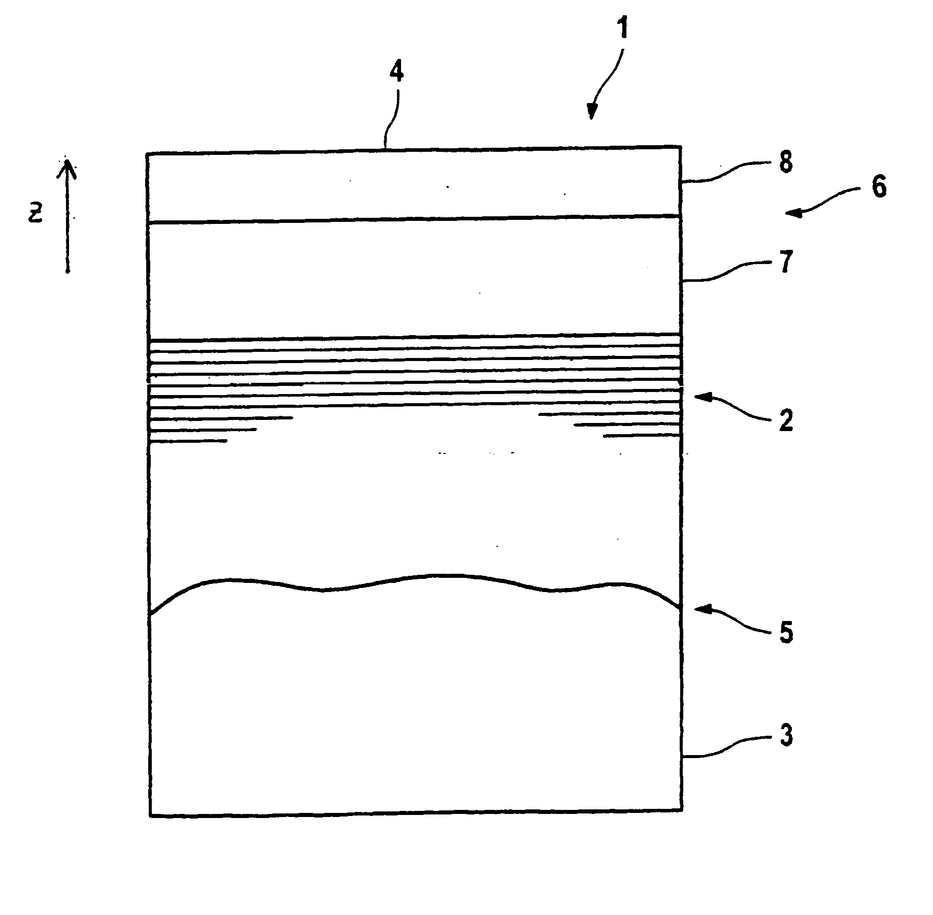
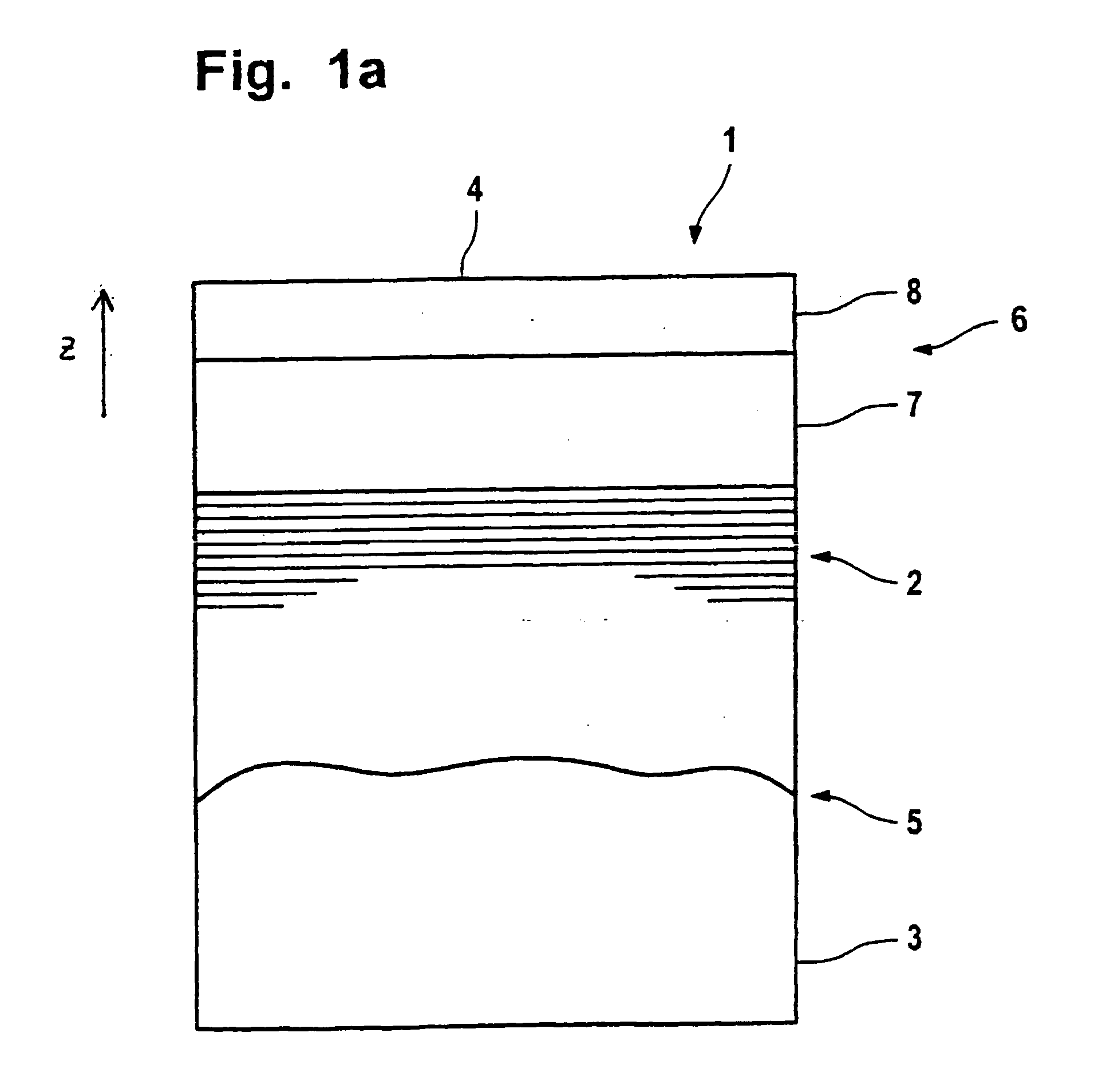
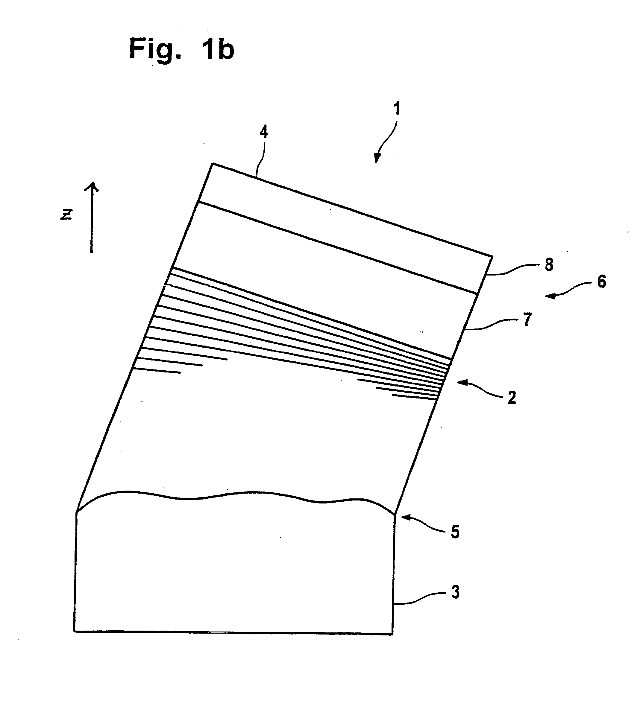
[0061]FIGS. 1a to c have already been explained.

[0062] In FIGS. 2 to 4, a first preferred embodiment of the invented optical element is described.

[0063]FIG. 2a shows the two-dimensional intensity distribution of incident EUV radiation for a first optical element with which the reflective optical element is to be utilized. The intensity increases from the outside to the middle.

[0064]FIGS. 2b and 2c show the intensity curve in the x and y direction corresponding to the broken lines drawn in FIG. 2a. This intensity curve in the xy-direction corresponds in monotonic manner to the thickness curve of the cover layer system. Where a high radiation intensity impinges on the reflective optical element, the cover layer system is also particularly thick. Where the intensity is less, the cover layer system is also thinner. Corresponding to FIGS. 1a-c, the thickness distribution designated as 7 pertains to the lower segment of the cover layer system and the thickness distribution designated a...


PUM


Abstract

In order to obtain optimal reflectivity on optical elements for the EUV and the soft X-ray range, multilayers constructed of a number of layers are used. Contamination or degradation of the surface leads to imaging defects and transmission losses. In the prior art, it has been attempted to counter a negative change in the surface by providing a cover layer system on the surface of the reflective optical element that should protect the surface. The invention renders the influence of the surface degradation manageable by a targeted selection of the distribution of thickness of the cover layer system, whereby at least one layer of the cover layer system has a gradient that is not equal to zero.

Description

CROSS REFERENCE [0001] This application is a continuation-in-part application of International Application No. PCT / EP2004 / 004368, filed Apr. 26, 2004 and published as WO 2004 / 097467 on Nov. 11, 2004, which claims the priority to German Application No. 103 19 005.8, filed Apr. 25, 2003.FIELD OF THE INVENTION [0002] The invention concerns a reflective optical element for the external ultraviolet and / or soft x-ray wavelength region with a cover layer system having at least one layer, whose spatial structure can be described in a Cartesian system of coordinates (x, y, z) with z=z(x, y). Other systems of coordinates are possible for describing the spatial structure. [0003] Moreover, the invention concerns an optical system or an EUV lithography device with at least two reflective optical elements for the extreme ultraviolet and / or soft x-ray wavelength region with at least one cover layer system. BACKGROUND OF THE INVENTION [0004] Multilayers composed of a plurality of layers are used to...

Claims


Application Information

Patent Timeline
IPC IPC(8): G01J1/00G02B1/10G02B5/08G03F7/20G21K1/06
CPCB82Y10/00G02B1/105G02B5/0883G02B5/0891G03F7/70958G21K1/062G02B1/14
Inventor WEDOWSKI, MARCO
Owner CARL ZEISS SMT GMBH
Why Eureka
Try Eureka