RF measurement feedback control and diagnostics for a plasma immersion ion implantation reactor

a technology of ion implantation reactor and measurement feedback, which is applied in the direction of individual semiconductor device testing, semiconductor/solid-state device testing/measurement, instruments, etc., can solve the problems of difficult boron dose determination from a measured current, difficult to precisely determine the atomic weight of the ions incident on the wafer, and difficult to dosimetry of the plasma immersion ion implantation reactor. achieve the effect of greater accuracy

Inactive Publication Date: 2006-04-27
APPLIED MATERIALS INC
View PDF99 Cites 137 Cited by
  • Summary
  • Abstract
  • Description
  • Claims
  • Application Information

AI Technical Summary

Benefits of technology

[0014] For greater accuracy, the method may further include transforming the RF voltage from the measure

Problems solved by technology

This is critical in an ion beam implant machine, because it employs a D.C. ion source, which is subject to significant drift in its output current, and the various grids and electrodes employed in the beam implant machine drift as well (due to the susceptibility of a D.C. source to accumulation of deposited material on component surfaces).
In contrast, plasma immersion ion implantation reactors present a difficult problem in dosimetry.
Typically, the atomic weight of the ions incident on the wafer cannot be precisely determined because such a reactor employs a precursor gas containing the desired ion implantation species as well as other species.
As a result, determining the boron dose from a measured current is difficult.
Another difficulty in implementing dosimetry in a plasma immersion ion implantation reactor is that the plasma ions impact the entire wafer continuously, so that it is difficult to effect a direct measurement above the wafer of the total ion current to the wafer.
A further difficulty encountered in some plasma immersion ion implantation reactors is the presence of electromagnetic noise or interference in the chamber that can prevent a precise measur

Method used


Image

  • RF measurement feedback control and diagnostics for a plasma immersion ion implantation reactor
  • RF measurement feedback control and diagnostics for a plasma immersion ion implantation reactor
  • RF measurement feedback control and diagnostics for a plasma immersion ion implantation reactor

Examples


Embodiment Construction

Introduction

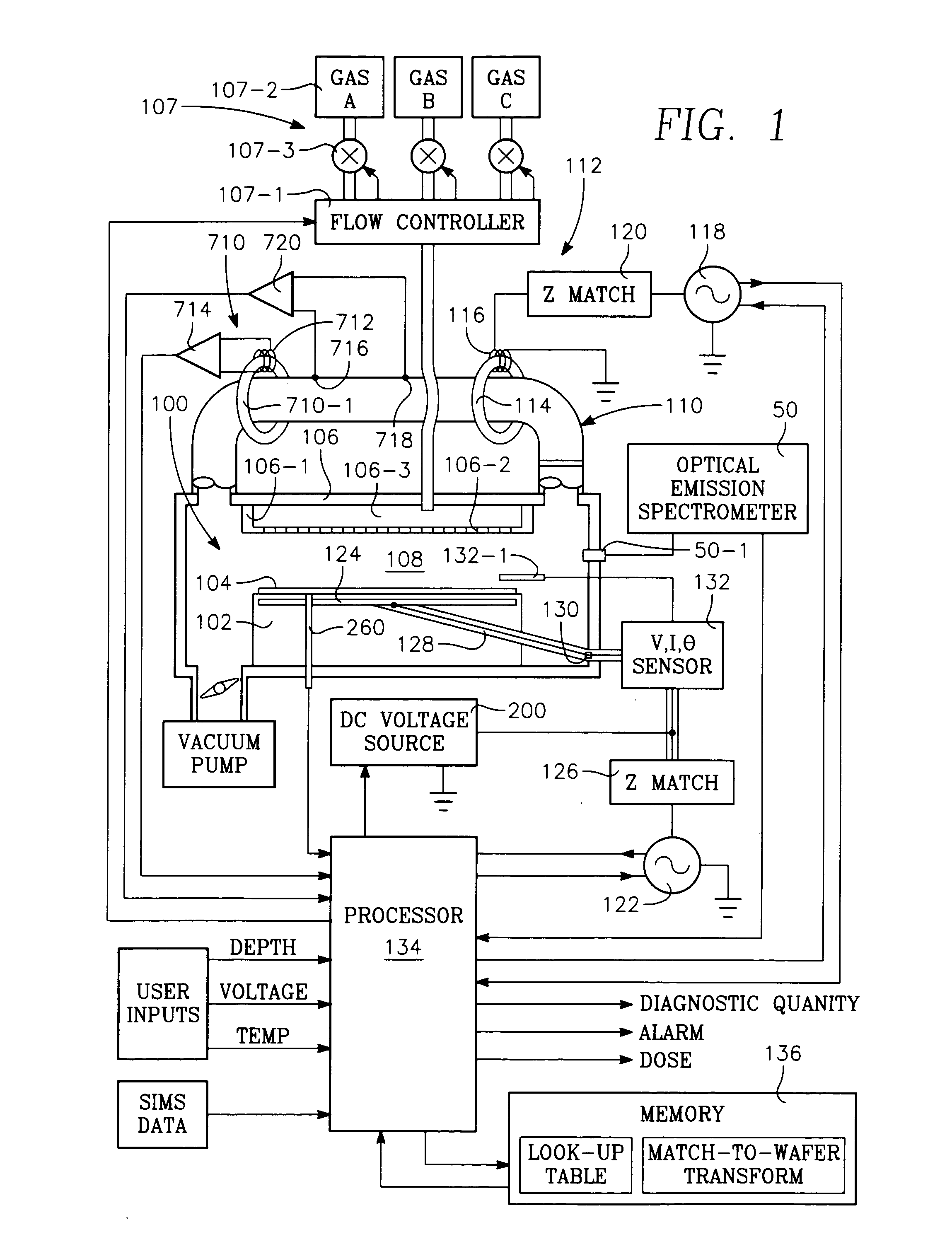
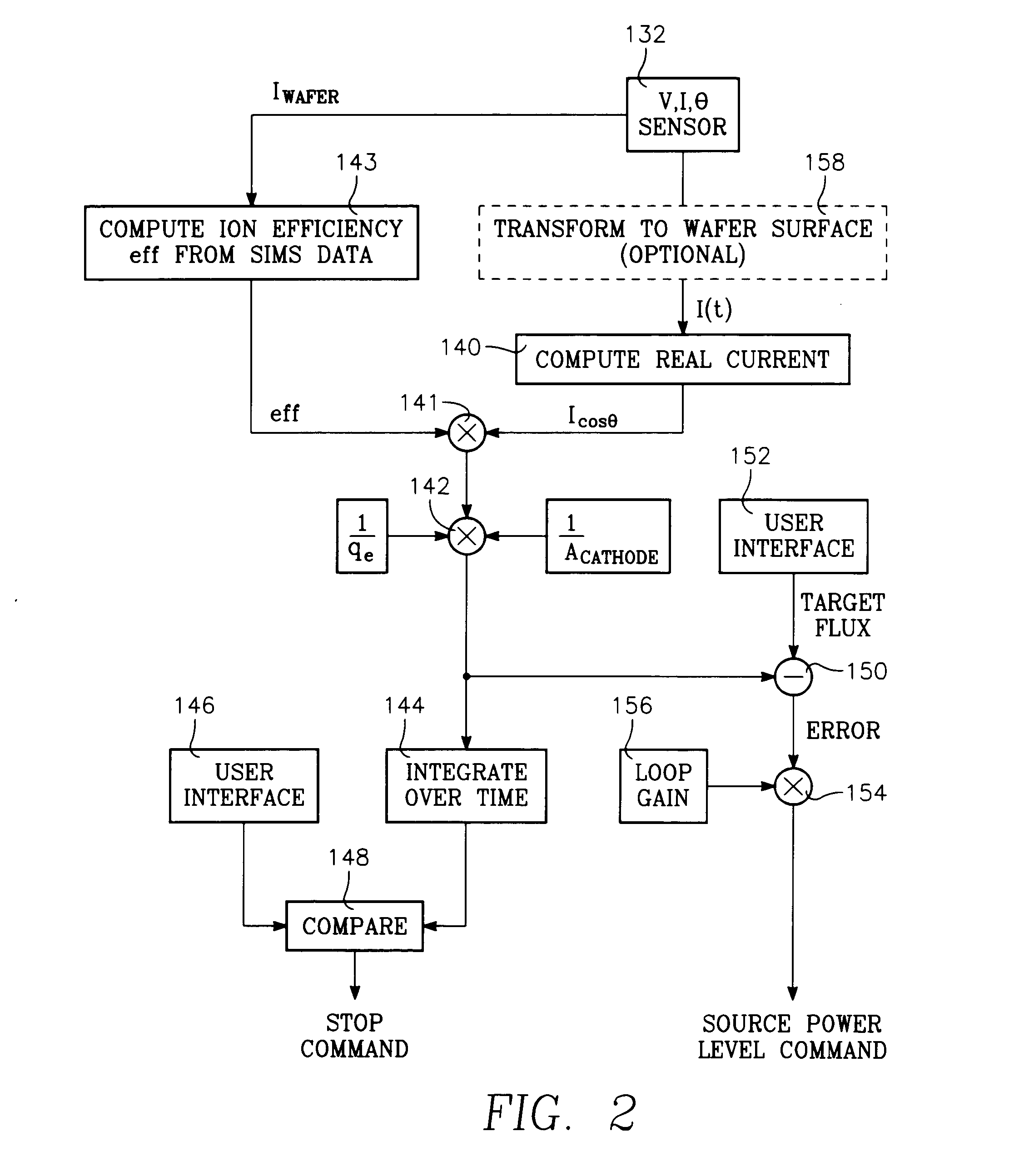
[0037] A method of measuring ion dose in a plasma immersion ion implantation reactor during ion implantation of a selected species into a workpiece includes placing the workpiece on a pedestal in the reactor and feeding into the reactor a process gas comprising a species to be implanted into the workpiece, and then coupling RF plasma source power to a plasma in the reactor. It further includes coupling RF bias power to the workpiece by an RF bias power generator that is coupled to the workpiece through a bias feedpoint of the reactor and measuring RF current at or near the feedpoint to generate a current-related value, and then integrating the current-related over time to produce a dose-related value.

[0038] The method may further include measuring RF voltage at or near the feedpoint.

[0039] The method may further include measuring the phase between said RF current at or near the feedpoint and the RF voltage at or near the feedpoint.

[0040] The method may include using ...


PUM

PropertyMeasurementUnit
Temperatureaaaaaaaaaa
Timeaaaaaaaaaa
Poweraaaaaaaaaa

Abstract

A method of measuring ion dose in a plasma immersion ion implantation reactor during ion implantation of a selected species into a workpiece includes placing the workpiece on a pedestal in the reactor and feeding into the reactor a process gas comprising a species to be implanted into the workpiece, and then coupling RF plasma source power to a plasma in the reactor. It further includes coupling RF bias power to the workpiece by an RF bias power generator that is coupled to the workpiece through a bias feedpoint of the reactor and measuring RF current at the feedpoint to generate a current-related value, and then integrating the current-related over time to produce an ion implantation dose-related value.

Description

BACKGROUND OF THE INVENTION [0001] Ion implantation processes in integrated circuit fabrication typically require instrumentation and control to achieve a desired ion dose on a semiconductor wafer. The dose is the total number of ions per unit area passing through an imaginary surface plane of the wafer. The implanted ions distribute themselves throughout the volume of the wafer. The principal variation in implanted ion density (number of ions per unit volume) occurs along the direction of the ion flux, usually the perpendicular (vertical) direction relative to the wafer surface. The distribution of ion density (ions per unit volume) along the vertical direction is referred to as the ion implantation depth profile. Instrumentation and control systems for regulating ion implant dose (ions per unit area) is sometimes referred to as dosimetry. [0002] Ion beam implant machines, which generate a narrow ion beam that must be raster-scanned over the surface of the wafer, typically implant ...

Claims


Application Information

Patent Timeline
IPC IPC(8): C23C14/00C23C16/52
CPCC23C14/48C23C14/54H01J37/321H01J37/32412H01J37/32935
Inventor COLLINS, KENNETH S.HANAWA, HIROJIRAMASWAMY, KARTIKAL-BAYATI, AMIRNGUYEN, ANDREWGALLO, BIAGIO
Owner APPLIED MATERIALS INC
Why Eureka
Try Eureka