
Case-hardening of stainless steel

a technology of stainless steel and hardening, applied in the direction of nanotechnology, coating, nanotechnology, etc., can solve the problems of reducing the free chromium content of the material, and affecting the corrosion performan

Inactive Publication Date: 2006-05-04
DANMARKS TEKNISKE UNIV DTU LEDELSESSEKRETARIATET
View PDF4 Cites 38 Cited by
  • Summary
  • Abstract
  • Description
  • Claims
  • Application Information

AI Technical Summary

Benefits of technology

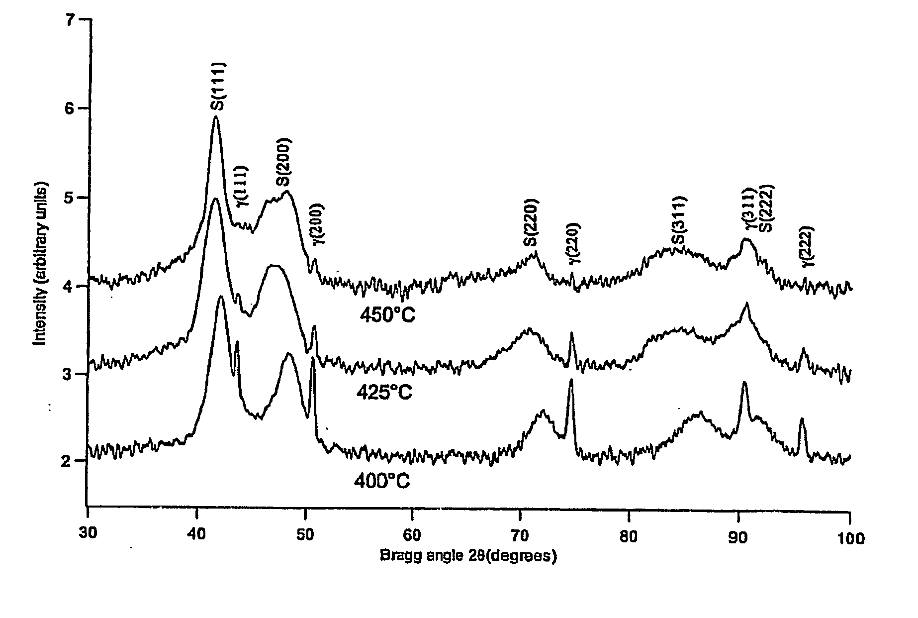
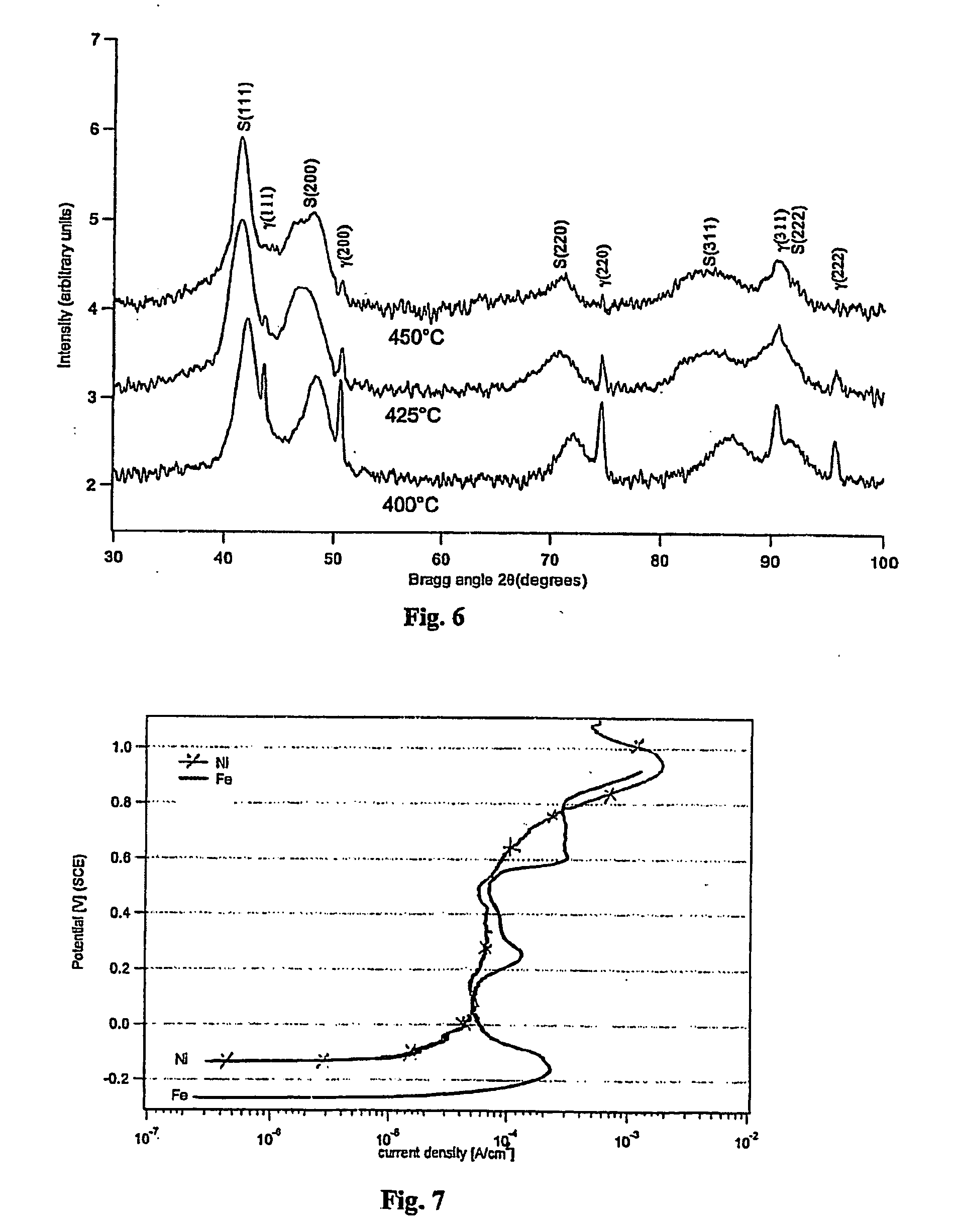
[0011] The object of the invention is to provide a new and improved method for case-hardening stainless steel. The object of the invention is obtained by a process according to the preamble of claim 1, wherein the top layer includes metal which is catalytic to the decomposition of the gas carrying the carbon or / and nitrogen atoms and which is one or more of the metals Ni, Ru, Co or Pd. The metal layer protects the stainless steel surface from oxidation and acts as a catalytic surface for the decomposition of the gas. As a result the process temperature can be kept below the temperature at which carbides and / or nitrides are formed, and the process can be finished within a reasonable period of time. After the thermo-chemical treatment, the catalytic metal layer can be removed to expose and repassivate the hardened stainless steel surface.
[0014] When stainless steel is treated with the method according to the invention, the harness and wear resistance are improved considerably without the deterioration of the corrosion properties.
[0017] EP 0248431 B1discloses a method where an austenitic stainless steel article is electroplated with iron before nitriding at 575° C. for 2 hours. As mentioned before, chromium nitrides are formed at this temperature. As disclosed on page 4, lines 13 to 18 of EP 0248431 B1, only the valve shaft of a valve is nitrided. The valve disk (Ventilteller) is protected from nitriding by an oxide layer in order not to reduce the corrosion resistance of the valve disk.
[0023] According to a preferred embodiment the calculated maximum average thickness of the nickel layer does not exceed 300 nanometer, preferably 200 nanometer. A nickel layer of this thickness is sufficient to prevent oxidation and to allow carbon and / or nitrogen atoms to diffuse through the nickel layer into the stainless steel to form a satisfactory S-phase layer.

Problems solved by technology

Stainless steel has excellent corrosion properties, but is relatively soft and has poor wear resistance, especially against adhesive wear.
Gas carburization, nitriding and nitro-carburizing of stainless steel involve some difficulties, as the passive layer, causing the good corrosion properties, acts as a barrier layer preventing carbon and / or nitrogen atoms from diffusing through the surface.
The formation of chromium carbides and / or chromium nitrides reduces the free chromium content in the material whereby the corrosion properties are deteriorated.
At this temperature, chromium nitrides are formed, whereby the corrosion properties are deteriorated.

Method used


Image

  • Case-hardening of stainless steel
  • Case-hardening of stainless steel
  • Case-hardening of stainless steel

Examples


example 1

Nitriding in Pure NH3 Gas, Austenitic Stainless Steel AISI 304

[0032] An article of austenitic stainless steel AISI 304 was nitrided in pure NH3 gas (maximum nitriding potential) for 17 hours and 30 minutes at 429° C. Heating to nitriding temperature was carried out in a hydrogen atmosphere (H2), whereafter the supply of the hydrogen gas was switched off, and the nitriding gas was supplied. Cooling to room temperature was carried out in argon gas (Ar) in less than 10 minutes. The article was analysed by optical microscopy and electron probe micro-analysis (EPMA). The formed layer was nitrogen S-phase and bad a layer thickness not exceeding 9 μm. The maximum concentration of nitrogen in the S-phase was more than 20 atom %. The analysis disclosed that no nitrides had precipitated.

example 2

Nitriding in Pure NH3 Gas, Austenitic Stainless Steel AISI 316, FIGS. 1 and 2

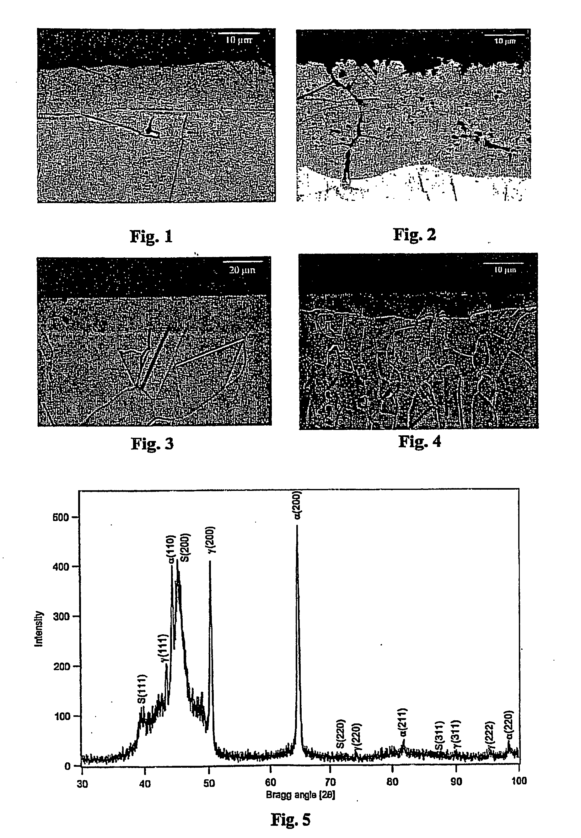
[0033] An article of austenitic stainless AISI 316 was treated as described in Example 1, but at a temperature of 449° C. for 20 hours. The article was analysed by light optical microscopy (LOM), X-ray diffraction analysis (XRD) and micro-hardness measurements. The LOM results are shown in FIG. 1. The formed layer consisted of nitrogen S-phase and had a layer thickness of 12 μm. The micro-hardness was more than 1500 HV (load 100 g). The untreated stainless steel had a hardness between 200 and 300 HV. No nitrides had precipitated.

[0034] An austenitic steel article, heated in ammonia to 480° C. and kept for 21 hours at this temperature, showed the development of chromium nitride CrN (and ferrite) close to the surface as well as locally in the S-phase layer (the dark regions in FIG. 2). This result indicates that a high temperature of 480° C. should be avoided to obtain a monophase S-phase layer.

example 3

Carburizing in Pure CO Gas, Austenitic Stainless Steel AISI 316, FIG. 3

[0035] An article of austenitic stainless AISI 316 was carburized in pure CO gas for 6 hours at 507° C. to form the carbon S-phase. Heating was carried out in a hydrogen atmosphere (H2), until the carburization temperature was obtained, and whereafter the supply of hydrogen was switched off and the CO gas was supplied. Cooling to room temperature was carried out in argon gas (Ar) in less than 10 minutes. The article was analysed by optical microscopy, X-ray diffraction analysis and micro-hardness measurements. The LOM results are shown in FIG. 3. The formed layer was carbon S-phase having a layer thickness of 20 μm (see FIG. 3). The micro-hardness of the surface was more than 1000 HV (load 100 g). No carbides had precipitated.


PUM

PropertyMeasurementUnit
thicknessaaaaaaaaaa
temperatureaaaaaaaaaa

Abstract

The invention relates to case-hardening of a stainless steel article by means of gas including carbon and / or nitrogen, whereby carbon and / or nitrogen atoms diffuse through the surface into the article. The method includes activating the surface of the article, applying a top layer on the activated surface to prevent repassivation. The top layer includes metal which is catalytic to the decomposition of the gas.

Description

TECHNICAL FIELD [0001] The present invention relates to a method according to the preamble of claim 1. BACKGROUND ART [0002] Thermo-chemical surface treatments of steel by means of carbon or nitrogen carrying gases are well-known processes, called case-hardening or carburization or nitriding. Nitro-carburization is a process in which a gas caring both carbon and nitrogen is used. These processes are traditionally applied to improve the hardness and wear resistance of iron and low alloyed steel articles. The steel article is exposed to a carbon and / or nitrogen carrying gas at an elevated temperature for a period of time, whereby the gas decomposes and carbon and / or nitrogen atoms diffuse through the steel surface into the steel material. The outermost material close to the surface is transformed into a layer with improved hardness, and the thickness of this layer depends on the treatment temperature and the treatment time. [0003] Stainless steel has excellent corrosion properties, bu...

Claims


Application Information

Patent Timeline
Patent Type & Authority Applications(United States)
IPC IPC(8): C23C8/22C23C8/26C23C8/32C23C10/02C23C8/38
CPCC23C8/02C23C8/22C23C8/26C23C8/32C23C8/38B82Y30/00
Inventor SOMERS, MARCEL A. J.CHRISTIANSEN, THOMASMOLLER, PER
Owner DANMARKS TEKNISKE UNIV DTU LEDELSESSEKRETARIATET
Learn More