
Digital communication method and digital communication device

a communication method and digital communication technology, applied in the field of digital communication methods and devices, can solve the problems of decrepit purification characteristics, degrading error rate, and dropping subscriber capacity, and achieve the effect of reducing the number of side lobe spectra, and increasing the error tolerance to communication channel nois

Inactive Publication Date: 2006-05-04
YOKOHAMA TLO +1
View PDF2 Cites 6 Cited by
  • Summary
  • Abstract
  • Description
  • Claims
  • Application Information

AI Technical Summary

Benefits of technology

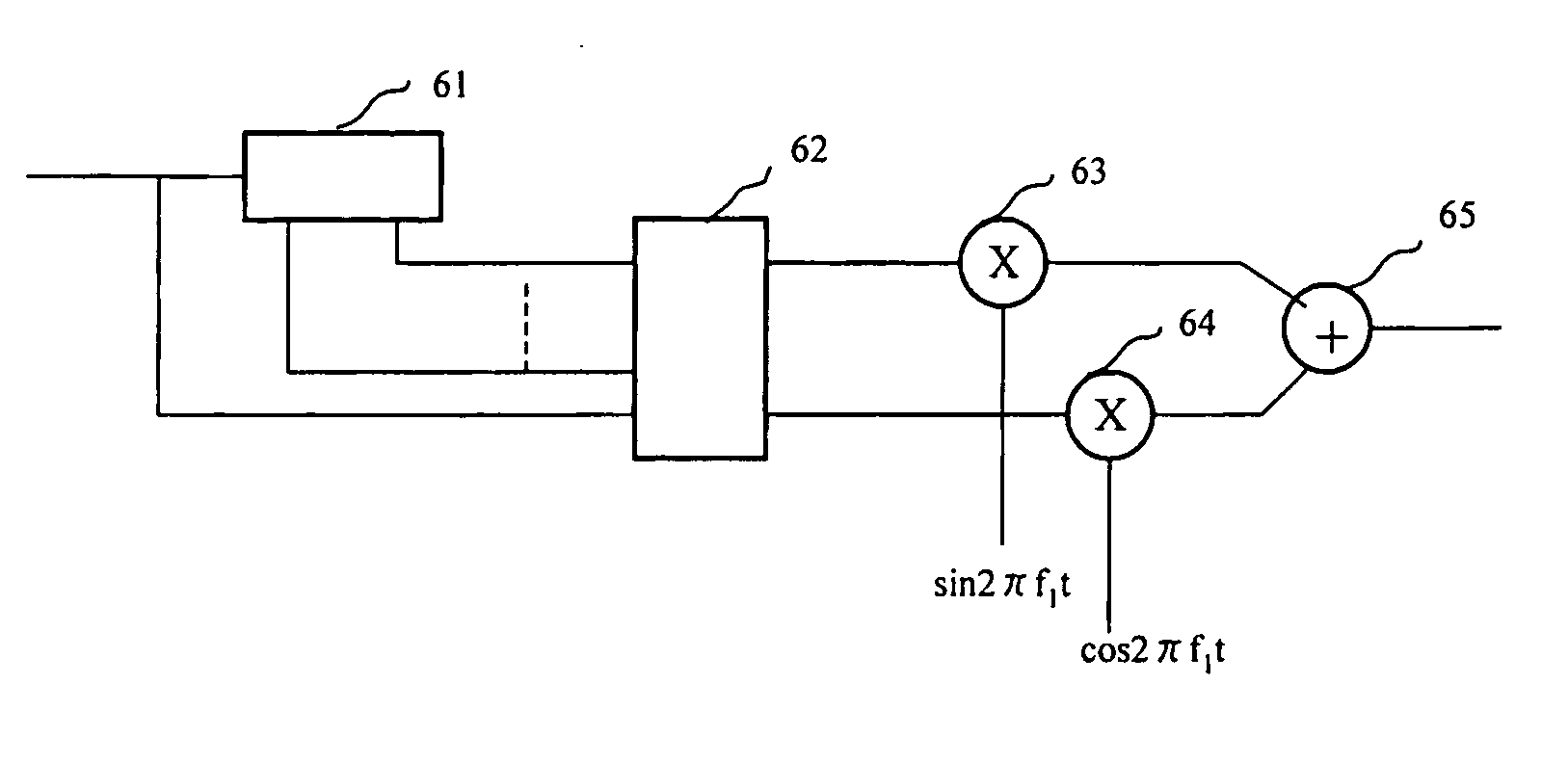
[0030] Since the amplitude variation of a three-phase modulated wave at symbol transition time is small, waveform distortion is minimal, and unnecessary side lobe spectra can be minimized even if this phase modulated wave is transmitted via a power amplifier with nonlinear characteristics. Further, even when phase modulating means outputs a constant envelope three-phase modulated wave, the binary digital information can be restored by the same demodulating means. When made into a constant envelope, the occupied frequency band increase slightly more than that of a three-phase modulated wave that is not a constant envelope, but frequency distortion resulting from a nonlinear power amplifier hardly occurs at all, and error tolerance to communication channel noise increases the same as in the case of three-phase modulation, which is not a constant envelope.

Problems solved by technology

Firstly, with regard to the first element, an outstanding bit error rate versus Eb / No can enable highly reliable communications to be carried out at the same transmission power.
That is, spurious characteristics degenerate greatly.
To ensure system-required spurious characteristics, channel spacing must be increased, causing a drop in subscriber capacity.
Further, since the output waveform is distorted when the input-output characteristics of a power amplifier are nonlinear, inter-symbol interference occurs at the receiver, degrading the error rate.
Conversely, when only the portions of the power amplifier input-output characteristics that are linear are used, the problem is that the power consumed by the power amplifier increases significantly, and the time that a mobile terminal can be used on a single charge, for example, continuous standby time, is greatly reduced.
However, the problem was that the FSK and GMSK bit error rate characteristics versus Eb / No were worse than for BPSK or QPSK, and, in addition, because the occupied radio frequency bandwidth was wide, frequency utilization efficiency was poor.
Further, the problem with multivalued PSK other than QPSK is that bit error rate characteristics rapidly degenerate in line with increases in the number of phases to be utilized, and another problem is that when the number of phases to be utilized is not treated as the power of 2, signal power utilization efficiency becomes increasingly lower due to the waste generated when binary digital information is mapped to a modulated phase.
Thus, most multivalued PSK other than QPSK are not being put to practical use.
However, the size of the circuitry of a Viterbi decoder increases exponentially together with the increase in the constraint length.
However, the elements of an input signal and output signal of a convolutional encoder generally coincide, and a convolutional code in which the input and output fields differ has not been studied much at all to date.
The problem, therefore, is that this offsets the effect of the coding gain of the convolutional code achieved by a practical decoding circuit size.
Thus, even the use of an optimum code configuration not disclosed in the above-mentioned Literature 3 can only achieve poor performance by which the error rate characteristics relative to Eb / No is 4 dB or greater despite that fact that the required bandwidth is the same as that of conventional methods that make use of ordinary convolutional code and QPSK.
In a mobile communications system, this side lobe spectrum causes problems, such as interference with other channels.
Or, if channel spacing is widened to avoid this interference with other channels, the problem is that the number of subscribers capable of talking simultaneously decreases.
However, because the instantaneous amplitude drops to 38% of the carrier wave amplitude at symbol transition time even when p / 4 shift QPSK is utilized, p / 4 shift QPSK does not solve for the problem of a side lobe spectrum interfering with other channels when the power amplifier possesses nonlinear characteristics.
That is, although it surpasses a QPSK system, which does not utilize error correction, by around 3 dB, when you take into consideration the fact that the coding gain of a conventional QPSK system that does use error correction is roughly 5.5 dB, the error rate characteristics of the Trellis coding 8-phase PSK system are markedly worse than those of conventional systems.
This is brought about by the fact that the error rate characteristics of 8-phase PSK on its own are poor.
As explained hereinabove, the problem with a digital communication device, which utilizes conventional QPSK or p / 4 shift QPSK, is that since modulated wave amplitude variation is great, a waveform is greatly distorted when it passes through a nonlinear amplifier, generating a side lobe spectrum.
This brings about the deterioration of spurious characteristics and an increase in the reception signal error rate.
Further, since the occupied frequency bandwidth is wide when GMSK, which is a constant envelope modulation system, and error correction are utilized, the problem here is that frequency utilization efficiency becomes poor.
Another problem is that Trellis coding constant envelope 8-phase modulation does not produce very favorable error rate characteristics versus Eb / No.

Method used


Image

  • Digital communication method and digital communication device
  • Digital communication method and digital communication device
  • Digital communication method and digital communication device

Examples


Embodiment Construction

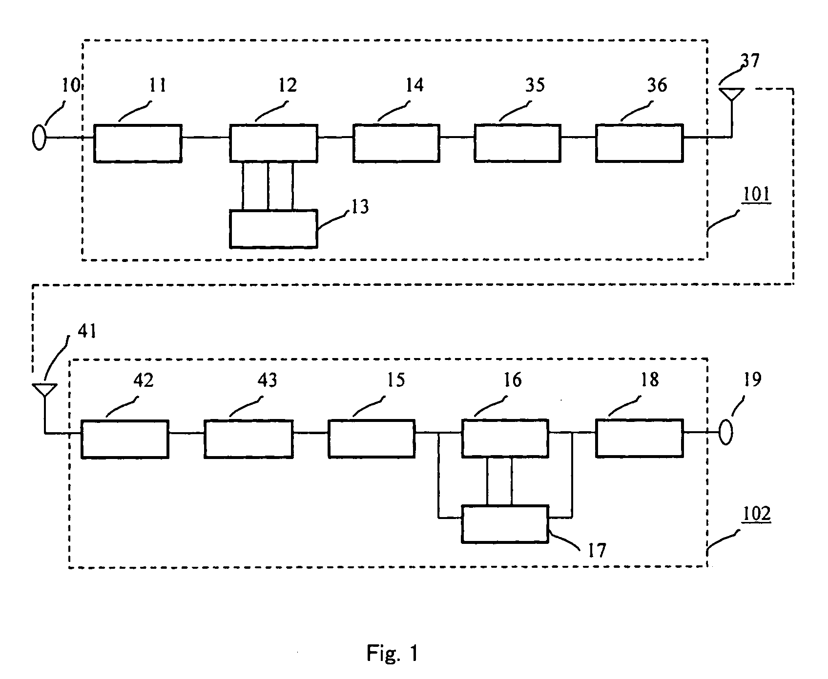
[0043] A digital communication method and digital communication device of the best mode for carrying out the present invention will be explained hereinbelow using the figures. Below, the aspects of the embodiment of the present invention will be explained in detail while referring to the figures.

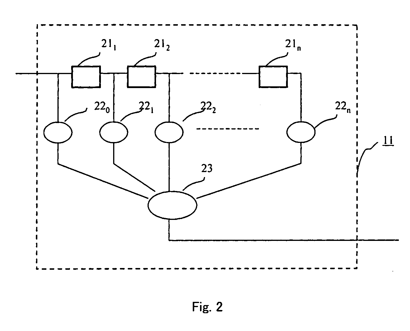
[0044]FIG. 1 is a simplified block diagram showing a first embodiment of a digital communication device of the present invention. In a transmitter 101, binary digital information inputted from a terminal 10 is sequentially inputted to an encoder 11. The encoder 11 outputs ternary digital information to a three-phase modulator 12 each time binary digital information is inputted. Sine waves whose phases differ only from one another are supplied from a signal generator 13 to the three-phase modulator 12, and the three-phase modulator 12 selects one of the signals supplied from the signal generator 13 in accordance with the ternary digital information inputted from the encoder 11.

[0045] If the...


PUM


Abstract

A digital communication device includes: a modulator having encoding means for converting two-dimensional digital information signal into a three-dimensional signal and phase modulation means for modifying the carrier phase in according to the three-dimensional signal; and a demodulator having phase demodulation means for detecting information on the three-dimensional signal from the received phase-modulated wave and demodulation means for deciding the two-dimensional digital information from the information on the three-dimensional signal. The digital communication device has a bit error ratio and an occupied radio band width equivalent to a digital communication device using the conventional QPSK or π / 4 shift QPSK and the error correction method and greatly improves the amplitude fluctuation. Moreover, the digital communication device can transmit a signal with a narrower occupied frequency band width while maintaining the same constant envelope characteristic as the GMSK using the conventional error correction code.

Description

TECHNICAL FIELD [0001] The present invention relates to a digital communication method and device utilized in digital wireless systems and so forth. BACKGROUND ART [0002] A digital modulation system is one that converts baseband digitalized information signals to the high frequency signals, making it an indispensable technology for a digital wireless system. Examples of digital modulation systems used in mobile communications are the PSK (Phase Shift Keying) system for making digital information correspond to the phase of a carrier wave, the FSK (Frequency Shift Keying) system for making digital information correspond to a frequency, and GMSK (Gaussian Minimum Shift Keying), which is a kind of FSK system that does not have carrier wave amplitude variations. [0003] The performance desired in a digital modulation system comprises three elements: outstanding bit error rate characteristics versus Eb / No; a narrow radio frequency occupied bandwidth; and small amplitude variations in a mod...

Claims


Application Information

Patent Timeline
Patent Type & Authority Applications(United States)
IPC IPC(8): H04B14/04H03M7/06H03M13/21H03M13/23H03M13/25H04L1/00H04L1/24H04L25/49H04L27/20H04L27/233H04L27/28
CPCH03M13/235H03M13/256H03M13/3983H04L1/0054H04L1/0059H04L27/2057H04L27/2332
Inventor NAKAMURA, MAKOTO
Owner YOKOHAMA TLO
Learn More