UV pulsed laser machining apparatus and method

a laser machining and pulsed technology, applied in laser beam welding apparatus, manufacturing tools, welding/soldering/cutting articles, etc., can solve the problems of high tooling cost, small internal circles and other intricate features, and inability to easily substitute less robust materials for polycarbonate faceplates, etc., to achieve the effect of maximizing cutting quality

Inactive Publication Date: 2006-05-11
WISCONSIN ALUMNI RES FOUND
View PDF17 Cites 23 Cited by
  • Summary
  • Abstract
  • Description
  • Claims
  • Application Information

AI Technical Summary

Benefits of technology

[0020] The preferred embodiment is directed to a laser-based cutting apparatus and method for processing polycarbonate sheets using photo-ablation. Preferably, an ultraviolet (UV) pulsed laser is employed. By controlling the parameters of the process, including the fluence, cutting speed, focus size, inked or similar coating of polycarbonate, use of a thin protective polyethelene film over the substrate, number of passes, focal length, focus...

Problems solved by technology

Cheaper, less robust material may not be readily substituted for the polycarbonate faceplate and only those polycarbonate faceplates manufactured to highest quality have met the industries' high aesthetic standards.
The various die-cutting processes work well for punching out features with large curvatures, however, the creation of intricate shapes, small internal circles and other intricate features present challenges due to the weak nature of the thin polycarbonate sheet and the limitations of mechanical dies.
Due to the necessity for quality products, and the limitations of the current manufacturing process, the polycarbonate face plate industry is plagued by high tooling costs.
The slightest misalignment of the precision tools used in the manufacture of the polycarbonate faceplates can destroy the quality of the die.
Furthermore, face plate manufacturers cannot maintain a die for long periods of time, as most industries utilizing faceplates, such as the appliance and automobile manufacturers, give their products face lifts on an annual or even biannual basis.
One commonly viewed problem of die systems is that cutting thicker sheets with steel roll dies can cause rolling and burring.
This is also a problem for thinner sheets when the steel rule die is duller, the sheet is not held taut, or there is a misalignment of the top and bottom dies.
The higher precision dies, however, are expensive to produce, and the slightest misalignment of the die causes the tools to crash, completely destroying the die.
The greatest problem with dies is exhibited in cutting small circles (less than ¼″ diameter) and internal curved features with very small widths.
While employing the aforementioned methods, and frequently sharpening the cutting surfaces of the die can improve the ability of the dies to cut the intricate shapes, a considerable amount of scrap is typically generated in the die cutting process.
Furthermore, the more irregular features on the steel rule cutting die, the more expens...

Method used


Image

  • UV pulsed laser machining apparatus and method
  • UV pulsed laser machining apparatus and method
  • UV pulsed laser machining apparatus and method

Examples


examples-parameters

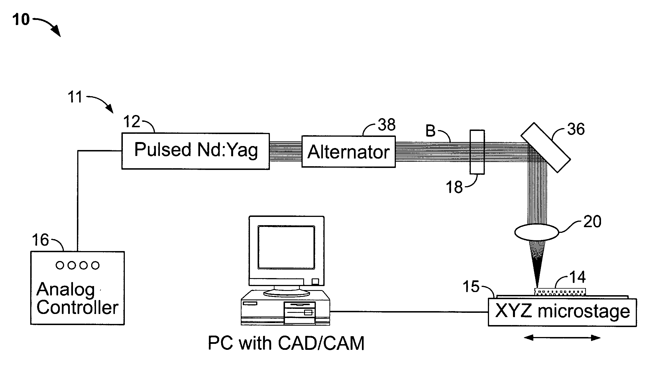
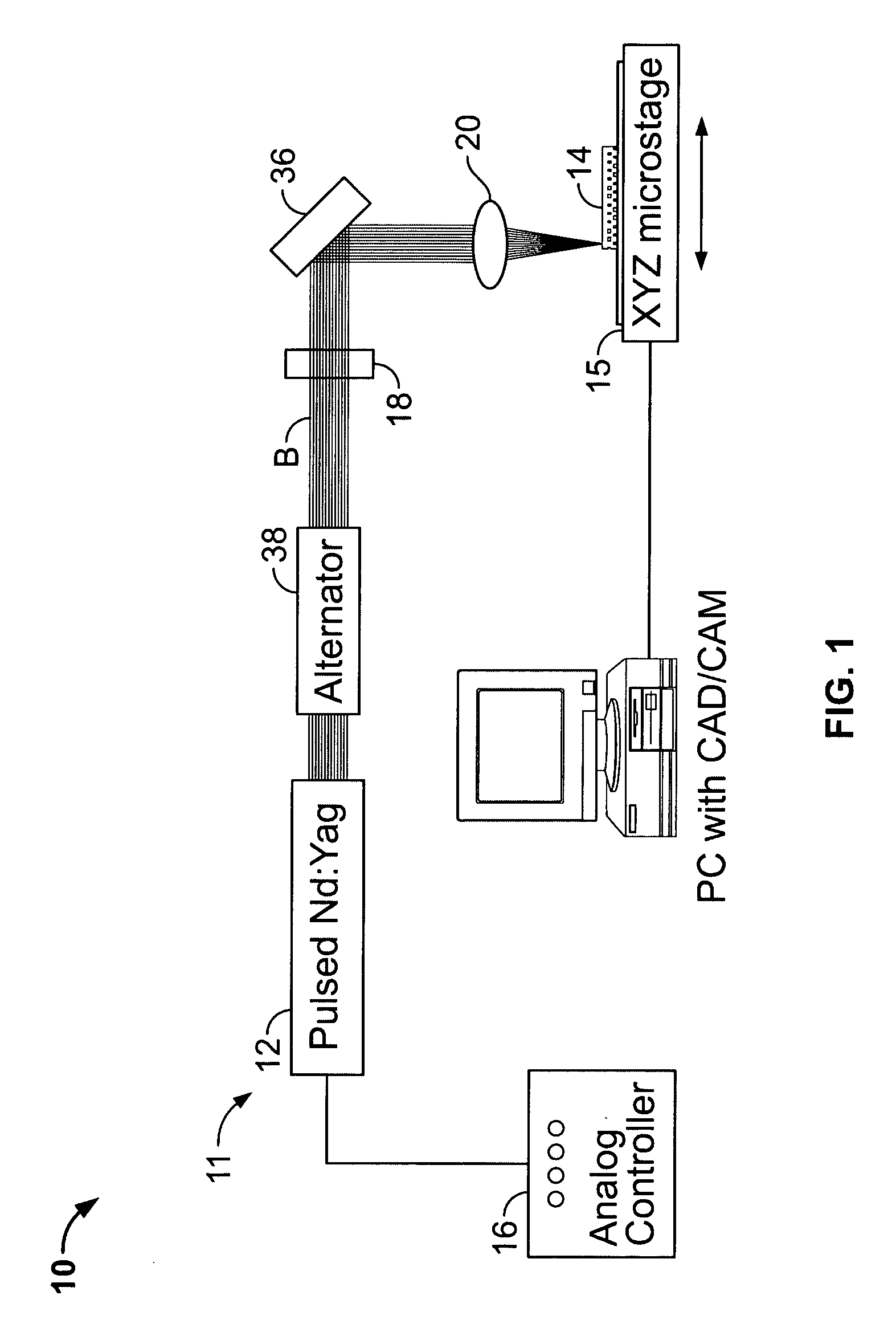
[0074] Several experiments were performed to determine the preferred parameters of the laser ablation process. Initially, the iris 38 was set to a theoretical desired diameter. An effective diameter of 5 mm can be used, but a 3.5 mm diameter was preferred. A 3.5 mm iris was found to produce a high quality beam that allows the focus position along the Z axis to be more easily found and adjusted than other diameters. Furthermore, by decreasing the iris diameter the most uniform and strongest portion of the beam can be captured and directly used in the processing operation. The 3.5 mm diameter iris assisted in developing a high quality beam. Most generally, and as understood in the art, a smaller iris can operate to block the less uniform outer edges of the normally distributed beam, leaving the center, higher energy portion of the beam to impinge upon the substrate.

[0075] In order to initiate the laser system 10, the laser 12 is activated, and the beam is conditioned by adjusting the...


PUM

PropertyMeasurementUnit
Lengthaaaaaaaaaa
Lengthaaaaaaaaaa
Fractionaaaaaaaaaa

Abstract

A method of cutting polycarbonate thin sheets generally less than 2 millimeters includes providing a source of pulse ultraviolet (UV) radiation. In operation, the method includes directing the UV radiation at the polycarbonate sheet to photo-ablate the polycarbonate sheet. A combination of parameters associated with the radiation may be selected, including at least one of a group of fluence, speed, coating of polycarbonate, number of passes, increasing or decreasing focal length, changing focus position and focus spot size.

Description

BACKGROUND OF THE INVENTION [0001] 1. Field of the Invention [0002] The present invention is directed to a tool and process for machining and / or cutting polycarbonate substrates, and more particularly, a tool employing an ultraviolet (UV) pulsed laser that processes based on photo-ablation. More specifically, a parameter window has been established allowing the skilled practitioner the ability to precisely and repeatably photo-ablate thin polycarbonate. [0003] 2. Description of Related Art [0004] In the United States alone, specialty printing is a 12.6 billion dollar industry. The manufacture of thin (0.2 to 2.0 mm) polycarbonate displays and faceplates make up a substantial portion of that business. Polycarbonate faceplates are used on a variety of consumer products, such as home appliances and automobile interiors, to provide permanent, highly visible exterior features. [0005] Many of the industries utilizing polycarbonate faceplates are highly competitive. Oftentimes only subtle ...

Claims


Application Information

Patent Timeline
IPC IPC(8): B23K26/38
CPCB23K26/0656B23K26/18B23K26/4065B23K26/009B23K26/0661B23K26/066B23K2103/42B23K2103/50
Inventor XIAOCHUN, LIHONGSEOK, CHOIPLATKOWSKI, JEFFREY S.
Owner WISCONSIN ALUMNI RES FOUND
Why Eureka
Try Eureka