
Stranded copper-plated aluminum cable, and method for its fabrication

Active Publication Date: 2006-05-18
F S P.-1
View PDF13 Cites 19 Cited by
  • Summary
  • Abstract
  • Description
  • Claims
  • Application Information

AI Technical Summary

Benefits of technology

[0013] An object of the invention is to propose a new stranded cable structure for conducting electrical current having simultaneously low electrical resistivity, good flexibility, a sufficiently high yield point, good electrical contact properties, good anti-corrosion properties for long term use under aggressive conditions, and good capacities for withstanding mechanical clamping for making electrical connections.
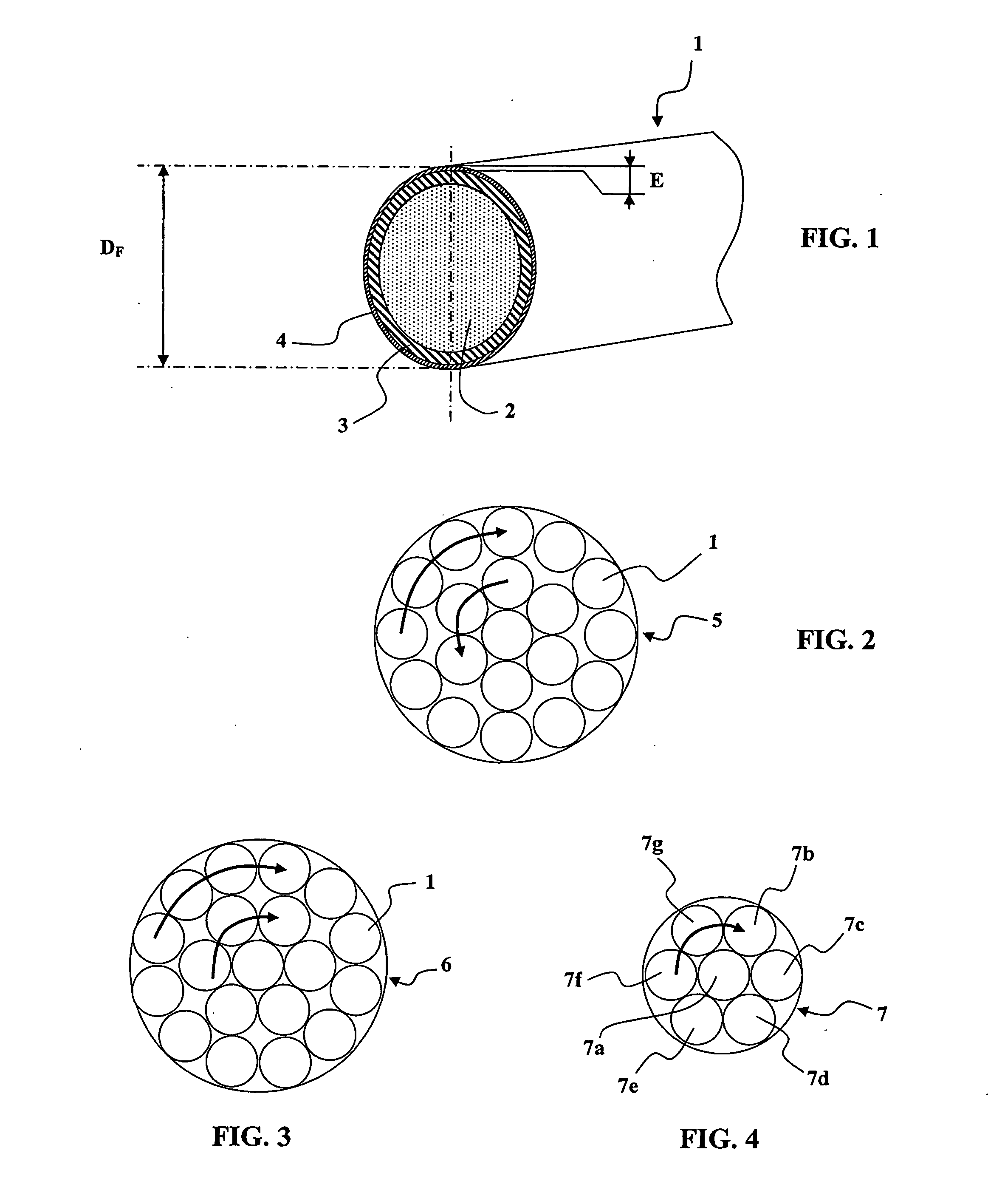
[0025] To increase the mechanical strength of the cable of small diameters, the conductor may advantageously comprise a central wire of nickel-plated copper alloy surrounded by six wires of nickel-plated copper-plated aluminum with a diameter of about 0.25 mm or about 0.20 mm.
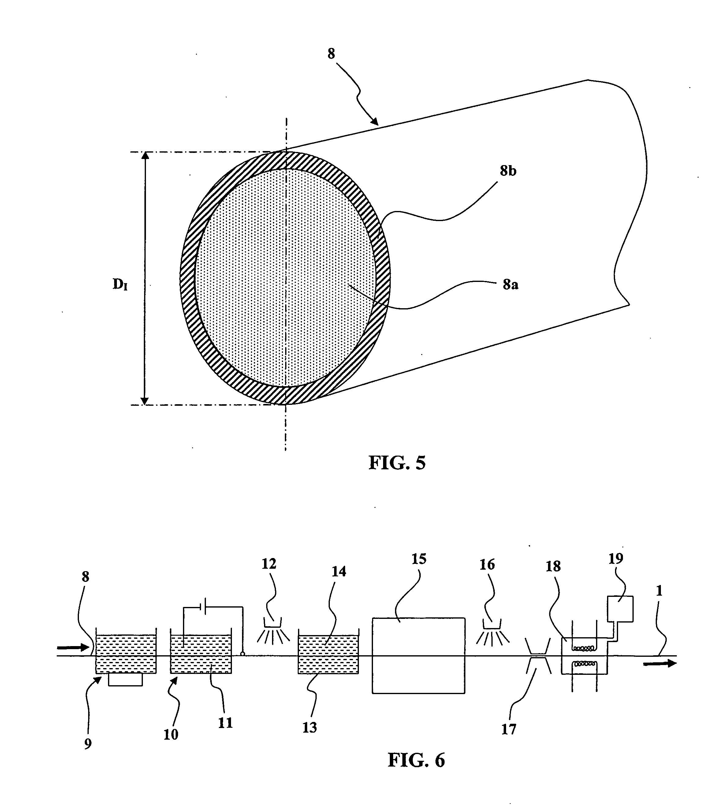
[0027] One problem to be solved is that of producing a continuous, adherent and sealed nickel layer on an industrial scale and at low cost. To this end, the invention proposes a copper-plated and nickel-plated aluminum wire fabrication procedure including the following steps:
[0036] In particular the above method prevents the appearance of oxides at the interfaces between the layers, in particular under the nickel layer, which oxides would subsequently be liable, during drawing, to produce discontinuities in the surface nickel layer and thereby reduce the protective and contact properties of that layer.
[0042] After a calibration step ao) of the above kind, the copper-plated aluminum wire blank may have, for example, a yield point less than or equal to about 20 daN / mm2 and an elongation from about 2% to about 3%. This prevents the appearance of lacunae or discontinuities in the surface nickel layer during drawing.

Problems solved by technology

One particular problem to be solved is that of providing a protective surface layer of nickel that is of satisfactory quality, both in terms of providing a seal and in terms of adhesion to the underlying layer of the conductor, but which does not significantly interfere with the other properties of the conductor, such as electrical conductivity, flexibility, weight, yield point.

Method used


Image

  • Stranded copper-plated aluminum cable, and method for its fabrication
  • Stranded copper-plated aluminum cable, and method for its fabrication
  • Stranded copper-plated aluminum cable, and method for its fabrication

Examples


Embodiment Construction

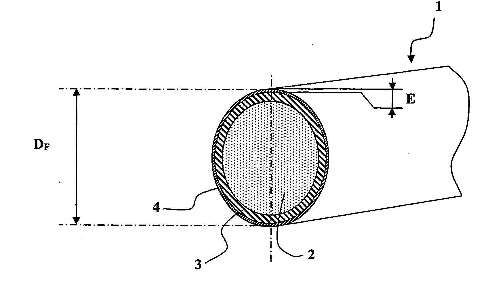
[0061] Consider first FIG. 1, which shows the structure of one embodiment of a conductive wire 1 of the invention. There may be seen an aluminum core 2 coated with an intermediate layer 3 of copper itself coated with a surface layer 4 of nickel.

[0062] The aluminum constituting the core 2 may be pure aluminum or an aluminum alloy. An alloy of 99.5% aluminum including at most 0.10% silicon and at most 0.40% iron may be preferred.

[0063] In applications in the aeronautical industry or the automotive industry, the wire may have a final total diameter DF from about 0.51 mm to about 0.20 mm. Other diameter values could be used, however, depending on the required characteristics.

[0064] The copper of the intermediate layer 3 may advantageously represent 15% by volume of the wire. This yields a wire having the following characteristics: a density at 20° C. of approximately 3.60 kilograms per cubic decimeter, a resistivity of 2.78 10-8 ohms per meter, a conductivity from 60% to 64% IACS, ge...


PUM


Abstract

Aluminum cable type electrical conductor comprising at least one stranded conductor based on conductive wires with an aluminum core coated with an intermediate layer of copper itself coated by a surface layer of nickel. The surface layer of nickel has a thickness from about 1.3 μm to about 3 μm, it has sufficient continuity to resist a polysulfide bath continuity test for at least 30 seconds without visible traces of attack of the copper appearing at ×10 magnification. This kind of conductor is particularly suitable in small diameters for conducting electricity in aircraft and motor vehicles.

Description

TECHNICAL FIELD OF THE INVENTION [0001] The present invention relates to copper-plated and nickel-plated aluminum or aluminum alloy conductors. It relates more particularly to electrical cables comprising at least one conductor with an aluminum or aluminum alloy core coated with a layer of copper itself coated with a layer of nickel. [0002] In the following description and the claims, the term “aluminum” refers in the broad sense to aluminum and its alloys. The term “conductor” refers to an electrically conductive body of elongate shape, the length whereof is large relative to its cross section, and which is generally in the form of a wire. [0003] Electrical conductors based on aluminum are widely used to transport electrical energy. Electrical wires and cables with an aluminum core may comprise an insulative material coating, and wires or individual strands may be assembled together to form the conductive core of a cable. [0004] Aluminum conductors used to transport and distribute ...

Claims


Application Information

Patent Timeline
IPC IPC(8): H01B11/06
CPCH01B1/023H01B1/026H01B9/008H01B13/0006H01B13/02
Inventor MICHEL EPOUSE ALLAIRE, ISABELLESALVAT, LOUIS
Owner F S P.-1
Learn More