
Colored radiation curable coating compositions for identifying telecommunications elements and telecommunications elements coated thereby

a technology of color radiation and coating composition, applied in the direction of cladding optical fibre, glass optical fibre, instruments, etc., can solve the problems of pigmented color coatings having a relatively short shelf life, affecting the color performance of optical fibers, and affecting the quality of optical fibers

Inactive Publication Date: 2006-05-18
ALCATEL LUCENT SAS
View PDF23 Cites 9 Cited by
  • Summary
  • Abstract
  • Description
  • Claims
  • Application Information

AI Technical Summary

Benefits of technology

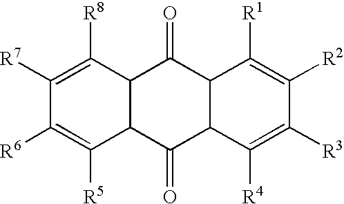
[0013] It is an object of the present invention to provide a colored, radiation curable composition for providing a durable color identifying coating on a transmission medium of a telecommunication element such as an optical fiber.
[0014] It is another object of the present invention to provide a telecommunication element which has a color identifying coating whose color does not bleed in the presence of typical cable filling compounds.
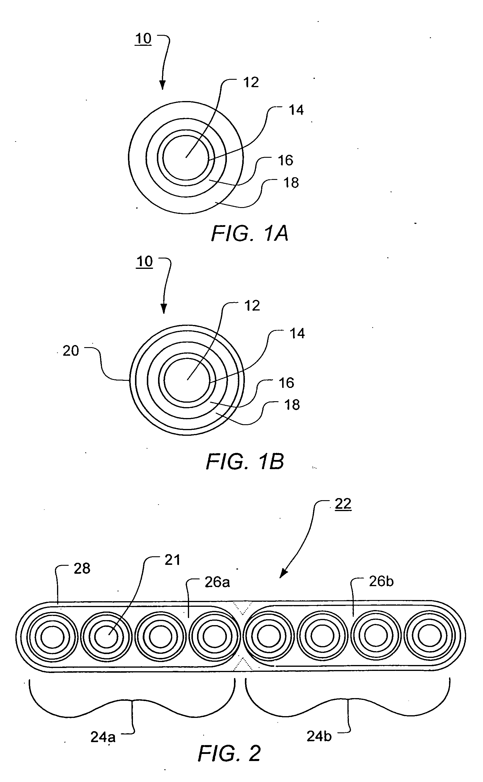
[0015] It is yet another object of the present invention to provide an optical fiber ribbon having a colored matrix whose color does not bleed in the presence of typical cable filling compounds.

Problems solved by technology

Unfortunately, the use of pigment particles to provide color in color coatings for optical fibers has presented manufacturing and performance problems.
As a result, pigmented color coatings have a relatively short shelf life.
In addition, the phase separation in a pigmented coloring system is further complicated by the concurrent agglomeration of pigment particles.
Undesirably, the presence of pigment particle agglomerates in a color coating on a coated optical fiber can induce micro-bending which results in transmission losses.
Unfortunately, the required high concentration inhibits the transmission of incident ultraviolet radiation which is necessary to cure the color coating material because the pigments refract, reflect and scatter the incident radiation.
The inhibition of the ultraviolet radiation results in a reduction in processing speed of the optical fiber along a manufacturing line and thereby increases production costs.
Also, the slow cure speed of pigmented color coatings causes the processing and the cure of these materials to be sensitive to minor changes in the thickness of the color coatings.
Dyes, however, are generally not preferred because they diffuse (bleed) out into common cable filling compounds resulting in a color loss.
While the entrapment results in a slowing of the bleeding process, the dyes nevertheless still bleed.
Over time, even with the entrapped polymeric dyes, the color imparted to the fibers is likely to be lost and if the color is lost from the fibers, then identification of each of the fibers becomes extremely difficult and time consuming in the field during fiber splicing.
The color imparted to the fibers will be lost over time if the dyes themselves lack stability.
The same problems mentioned above with respect to colored optical fibers apply to colored optical fiber ribbons.

Method used


Image

  • Colored radiation curable coating compositions for identifying telecommunications elements and telecommunications elements coated thereby
  • Colored radiation curable coating compositions for identifying telecommunications elements and telecommunications elements coated thereby
  • Colored radiation curable coating compositions for identifying telecommunications elements and telecommunications elements coated thereby

Examples


example 1

Yellow Oligomer

[0097] 202.89 g of Milliken REACTINT™ dye yellow X15 was added dropwise to a mixture of 67.44 g isophorone diisocyanate (IPDI) and dibutyltin dilaurate that had been heated to 40° C. Care was taken that the exothermic reaction did not heat above 45° C. by controlling the addition rate. The total time taken for addition was two hours. After the last addition of IPDI, 200 g of 1,6 hexanediol diacrylate (HDODA) was added as a reactive diluent to lower viscosity along with 4.4 g of inhibitor 2,6-Di-tert-butyl-4-methylphenol. This mixture was maintained at 40° C. for two hours before addition of 35.24 g 2-hydroxyethyl acrylate (HEA) dropwise with the temperature maintained below 50° C. by controlling the rate of addition of HEA. One hour after addition, there was no detectible isocyanate peak at 2270 cm−1 as observed by FTIR. The resulting urethane acrylate oligomeric reaction product has a yellow color.

example 2

Blue Oligomer

[0098] 152.09 g of Milliken REACTINT™ dye blue X3LV was added dropwise to a mixture of 101.13 g isophorone diisocyanate (IPDI) and 2.98 g dibutyltin dilaurate that had been heated to 40° C. Care was taken that the exothermic reaction did not heat above 45° C. by controlling the addition rate. The total time taken for addition was two hours. After the last addition of IPDI, 200 g of 1,6 hexanediol diacrylate (HDODA) was added as a reactive diluent to lower viscosity along with 2.03 g of inhibitor 2,6-di-tert-butyl-4-methylphenol. This mixture was maintained at 40° C. for two hours before addition of 52.96 g 2-hydroxyethyl acrylate (HEA) dropwise with the temperature maintained below 50° C. by controlling the rate of addition of HEA. Two hours after addition, there was no detectible isocyanate peak at 2270 cm−‘as observed by FTIR. The resulting urethane acrylate oligomer reaction product has a blue color.

example 3

Black Oligomer

[0099] 226.67 g of Milliken REACTINT™ dye black X95AB was added dropwise to a mixture of 93.30 g isophorone diisocyanate (IPDI) and 2.74 g dibutyltin dilaurate that had been heated to 40° C. Care was taken that the exothermic reaction did not heat above 45° C. by controlling the addition rate. The total time taken for addition was about two hours. After the last addition of IPDI, 200 g of tetrahydrafuran (THF) solvent was added as a reactive diluent to lower viscosity along with 2.38 g of inhibitor 2,6-di-tert-butyl-4-methylphenol. This mixture was maintained at 40° C. for two hours before addition of 48.78 g 2-hydroxyethyl acrylate (HEA) dropwise with the temperature maintained below 50° C. by controlling the rate of addition of HEA. Two hours after addition, there was no detectible isocyanate peak at 2270 cm−1 as observed by FTIR. The THF solvent was then removed via rotovap vacuum technique at room temperature over a 10 h period until a weight equal to the original...


PUM

PropertyMeasurementUnit
weight percentaaaaaaaaaa
viscosityaaaaaaaaaa
temperatureaaaaaaaaaa

Abstract

A telecommunication element having a durable color identifying polymeric coating thereon is disclosed. The telecommunication element comprises an elongated communication transmission medium, such as an optical fiber or an optical fiber ribbon, and a radiation cured polymeric coating having an identifying color applied on at least a portion of the transmission medium. The identifying color in the polymeric coating is provided by chromophore molecules that are covalently bonded thereto. Coating compositions and a method are also disclosed.

Description

CROSS-REFERENCE TO RELATED APPLICATION [0001] This is a divisional of application Ser. No. 09 / 870,482, filed Jun. 1, 2001, which is a continuation-in-part of application Ser. No. 09 / 360,951, filed Jul. 27, 1999, the entire disclosures of which are expressly incorporated herein by reference.BACKGROUND OF THE INVENTION [0002] 1. Field of the Invention [0003] The present invention relates to radiation curable coatings for telecommunications elements such as optical fibers and optical fiber ribbons. More particularly, the present invention relates to colored radiation curable coating compositions for producing cured coatings on a telecommunications element, the coating compositions having an identifying color provided by dye molecules which are covalently bonded to the cured coating. [0004] 2. Description of Related Art [0005] For many years now, optical fibers have been used as a reliable transmission medium in telecommunications cables. Typically, an optical fiber comprises a core, a ...

Claims


Application Information

Patent Timeline
Patent Type & Authority Applications(United States)
IPC IPC(8): D02G3/00C03C25/10G02B6/02
CPCC03C25/102C03C25/106Y10S522/904Y10T428/2933G02B6/02395Y10T428/2947Y10T428/2938Y10S522/905C03C25/475
Inventor GREER, ROBERT W. IV
Owner ALCATEL LUCENT SAS
Learn More