
Optical system and use thereof for detecting patterns in biological tissue

a biological tissue and optical system technology, applied in the field of optical systems, can solve the problems of little improvement in diagnostic accuracy, visual diagnosis alone may not be particularly accurate for early detection, and foregoing approach does not provide additional data to the physician

Inactive Publication Date: 2006-05-18
JOULE MICROSYSTEMS CANADA INC
View PDF1 Cites 42 Cited by
  • Summary
  • Abstract
  • Description
  • Claims
  • Application Information

AI Technical Summary

Benefits of technology

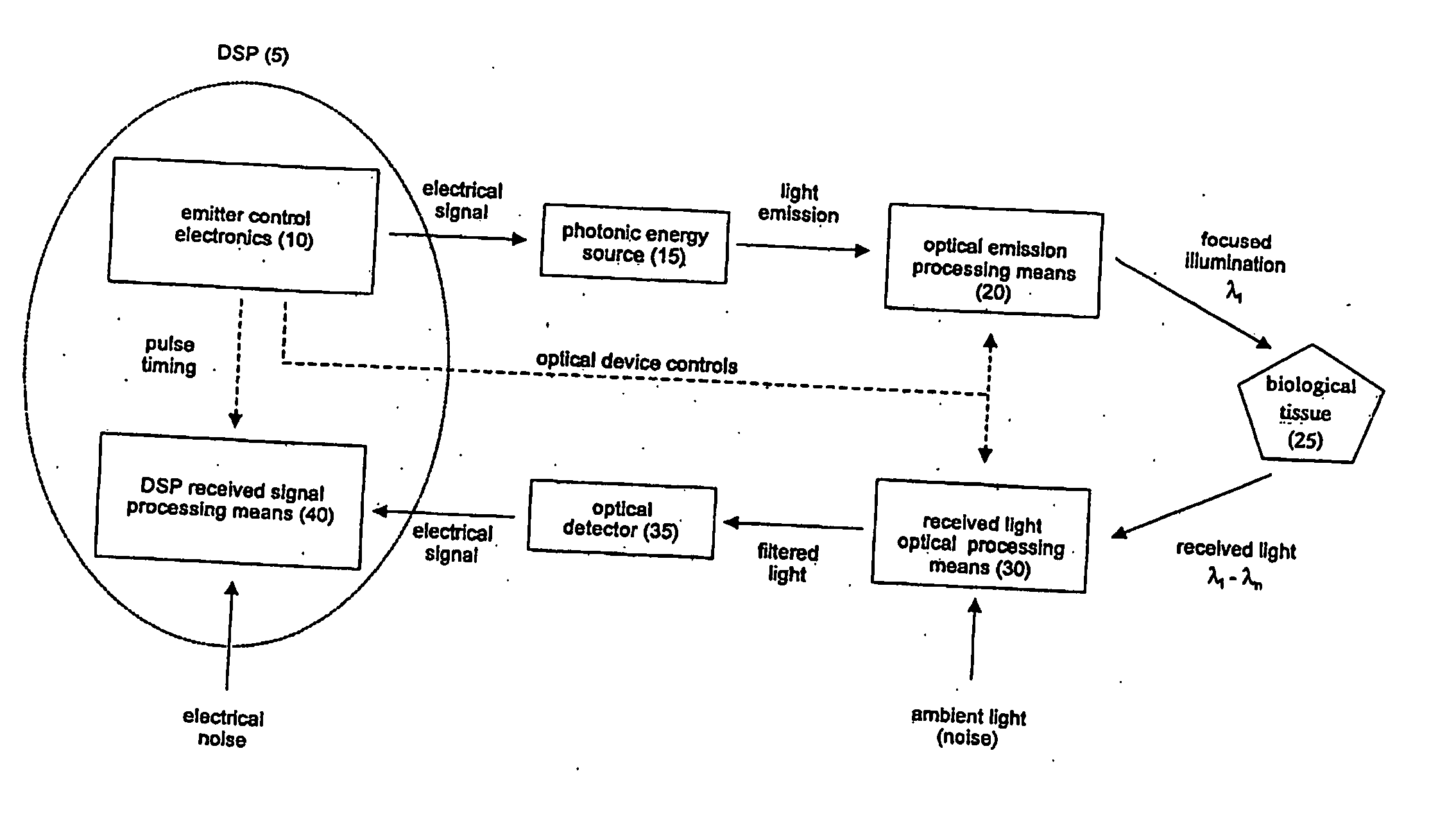
[0011] An object of the present invention is to provide an optical system and use thereof for detecting optical patterns in biological tissue. In accordance with one aspect of the present invention, there is provided an optical system for detecting optical characteristics of biological tissue, said optical system comprising: a photonic energy source for emitting electromagnetic radiation, wherein said photonic energy source is controlled by a digital signal processing means; an optical emission processing means for receiving electromagnetic radiation from the photonic energy source and transmitting one or more illumination wavelengths to the biological tissue, wherein the optical emission processing means is controlled by the digital processing means; an optics assembly providing a means for aligning emitter optics of the optical emission processing means with detector optics of a received light optical processing means; a received light optical processing means for collecting and isolating one or more wavelengths of received electromagnetic radiation from the biological tissue and transmitting the isolated one or more wavelengths of received electromagnetic radiation to an optical detector, wherein said received light optical processing means is controlled by the digital signal processing means; an optical detector for sensing and converting the isolated one or more wavelengths of received electromagnetic radiation into an electrical signal; and digital signal processing means to perform match filtering of the electrical signal received from the optical detector and for controlling the functionality of the photonic energy source, the optical emission processing means and the received light optical processing means.
[0012] In accordance with another aspect of the present invention, there is provided a use of an optical system for generating a pattern of optical characteristics of biological tissue, said optical characteristics being reflectance and fluorescence characteristics of the illuminated biological tissue, said optical system comprising: a photonic energy source for emitting electromagnetic radiation, wherein said photonic energy source is controlled by a digital signal processing means; an optical emission proc

Problems solved by technology

Visual diagnosis alone may not be particularly accurate for early detection of skin cancer since many skin conditions have a similar appearance under white light.
Although reflectance imaging has led to improvements in the registration, recording, and documentation of skin lesions, there has been little improvement in the diagnostic accuracy.
The foregoing approach does not provide any additional data to the physician making the visual assessment because it is still based on the reflectance pattern of a lesion under white light illumination, which is essentially the same pattern a human observer sees.
However, the inconvenience due to delays in processing of film images containing these reflectance patterns, renders this technique impractical for everyday use.
It is also incapable of detecting Raman scattering.
This device however can have limited detection capabilities due to noise entering the system, in terms of both stray light parameters and internal electronic noises.

Method used


Image

  • Optical system and use thereof for detecting patterns in biological tissue
  • Optical system and use thereof for detecting patterns in biological tissue
  • Optical system and use thereof for detecting patterns in biological tissue

Examples


example i

Spectrometer Incorporating a Matched Filter Receiver

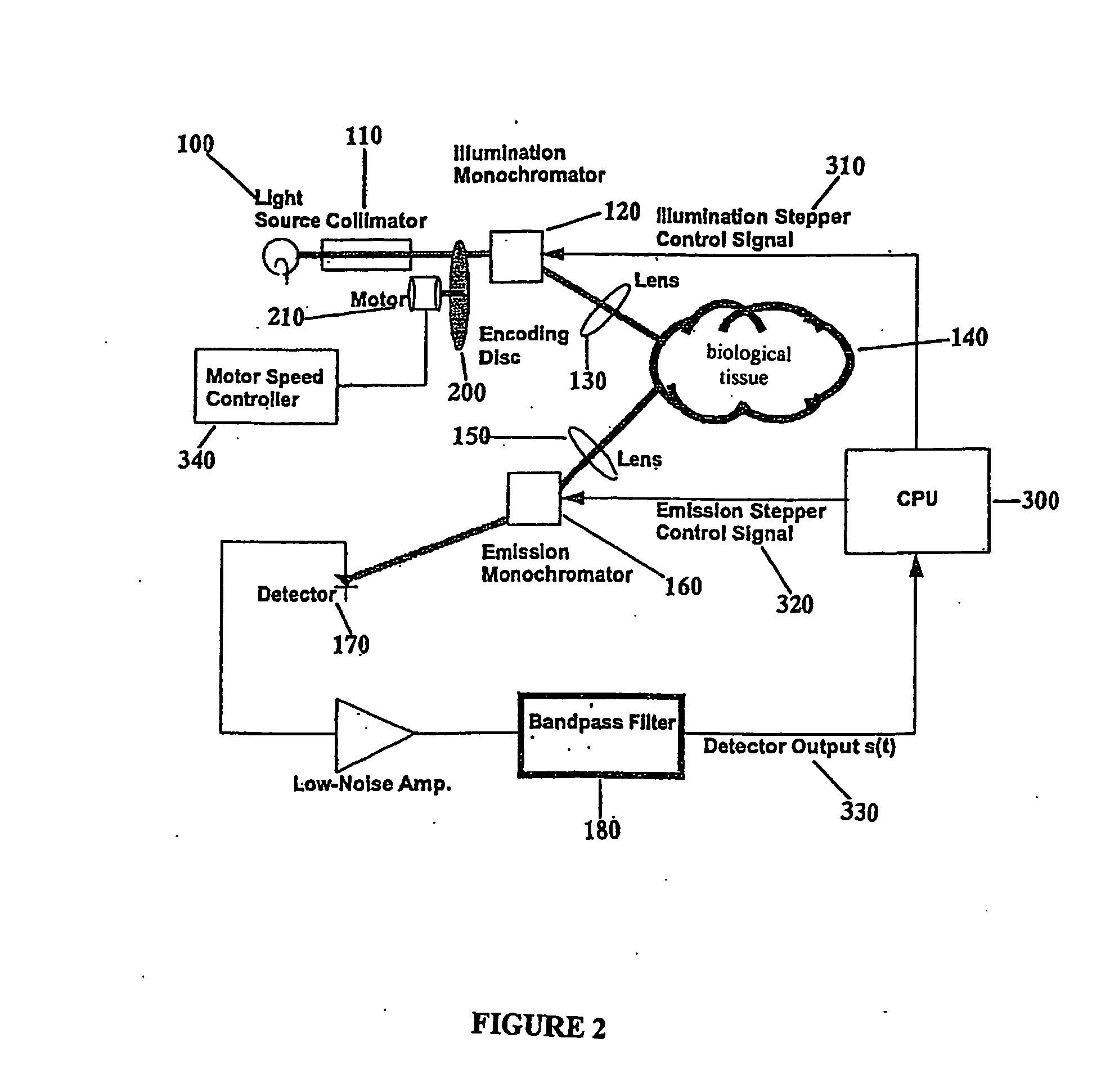
[0128] One embodiment of the present invention is shown in FIG. 19 and comprises a light source, for example, a miniature Xenon bulb that has an emission spectrum approximately equal to that of a 6000 ° K Blackbody with a few discrete spectral lines. The light is collimated and modulated by a chopper wheel, which provides a 500 Hz On-Off modulation to the light entering the Illumination Monochromator. The Illumination Monochromator operating under the control of the CPU sweeps the illumination wavelength from 250 nm to 800 nm in steps of 10 nm. This illumination is focused onto the Area of Interest, of the biological tissue. The Emission Monochromator operating under the control of the CPU sweeps the illumination wavelength from 250 nm to 800 nm in steps of 10 nm. It is controlled in such a way that for every illumination wavelength sample λi, it sweeps over the range of wavelengths greater than or equal to λi. A Ga—As photodiode ...

example ii

[0131] One embodiment of this invention comprises an optical system comprising a spectrometer, an electronic light modulator and digital signal processing means, including: a) a light emitting diode (LED), as the illumination light source, which is controlled by said digital signal processing means to emit a radiation bandwidth ranging from 380 to 500 nanometers; b) a stepper motor controlled, grating monochromator which is controlled by said digital signal processing means to receive light from the illumination device and to deliver the Nth wavelength in a pulse sequence; c) an optical fibre probe that is coupled to the monochromator with collimating and focusing elements that delivers the Nth wavelength to the biological tissue, located in an assembly that orients the illumination optics with that of the collecting optics such that they are at a constant angle to each other; d) collecting means for gathering the resultant radiation of the Nth wavelengths and delivering the informa...

example iii

[0134] In one embodiment of the present invention an optical system can be designed with the ability to control the wavelength of the scan (illumination radiation) including modulation techniques. This type of optical system can provide maximum optical flexibility in relation to research and diagnostic applications.

[0135] An embodiment of the optical system designed for this scenario comprises: a digital signal processing means which is integrated into a computing device with the emitter control electronics comprising pulse code software to create a synchronous pulse for direct modulation of the optical emission processing means frequency and the received signal processing means incorporating a signal correlation match filter; a flashlamp providing the photonic energy source; optical emission processing means incorporating a frequency modulator circuit for modulating the illumination radiation, a refractive or diffractive optical system whereby the optical centre wavelength is chos...


PUM


Abstract

The present invention provides an optical system comprises a scanning spectrometer incorporating an electronic light modulator and digital signal processing means. The spectrometer technique combined with optical signal encoding provides the ability to obtain spectral signatures and identify optical patterns of biological tissue. One example of biological tissue scanning includes techniques such as identification of optical patterns of normal and abnormal tissues in addition to the delineation of these spectral patterns between the abnormal and normal tissue. Due to an enhanced signal-to-noise ratio provided by the optical system according to the present invention, this optical system can detect patterns in biological tissue that may be more subtle than those patterns that would be possible to obtain with currently available optical systems.

Description

FIELD OF THE INVENTION [0001] This present invention pertains to the field of optical systems, and in particular to optical systems used for detecting patterns in biological tissue. BACKGROUND OF THE INVENTION [0002] Currently, clinical diagnosis of skin disease is generally accomplished by visual inspection under white light illumination. In this process, the reflectance light of a skin lesion is examined. Visual diagnosis alone may not be particularly accurate for early detection of skin cancer since many skin conditions have a similar appearance under white light. Therefore, when a suspect lesion is identified by visual examination, a biopsy is often performed for a definitive diagnosis. This is because it is crucial to diagnose skin pre-cancer or cancer at an early stage when it is curable. Thus, it is important to improve the clinical diagnosis of suspected skin lesions so as to avoid unnecessary skin biopsies. [0003] Several approaches have been tried to improve dermatological...

Claims


Application Information

Patent Timeline
IPC IPC(8): A61B6/00A61B5/00
CPCA61B5/0059
Inventor MCCONNELL, PETER R.H.ADAMS, BRUCE W.
Owner JOULE MICROSYSTEMS CANADA INC
Learn More