Cell mimic platform and method

a cell mimic and microfluidic technology, applied in the field of microfluidic devices, can solve the problems of difficult comparison of the results of dilute solution studies with the actual interactions inside the cell, crowded environment within the cell, anomalies in diffusion, etc., and achieve the effect of easy capture of the basic characteristics of the cellular nano-environmen

Active Publication Date: 2006-05-25
WISCONSIN ALUMNI RES FOUND
View PDF1 Cites 11 Cited by
  • Summary
  • Abstract
  • Description
  • Claims
  • Application Information

AI Technical Summary

Benefits of technology

[0009] It is a still further object and feature of the present invention to provide a microfluidic-based cell mimic platform and a method of mimickin

Problems solved by technology

It can be appreciated that accommodating all these materials in a small volume results in a crowded environment within the cell.
These traps or barriers result in anomalies in diffusion that have been observed both in cytoplasm and in organelles.
Given the complexity of the cel

Method used


Image

  • Cell mimic platform and method
  • Cell mimic platform and method
  • Cell mimic platform and method

Examples


Embodiment Construction

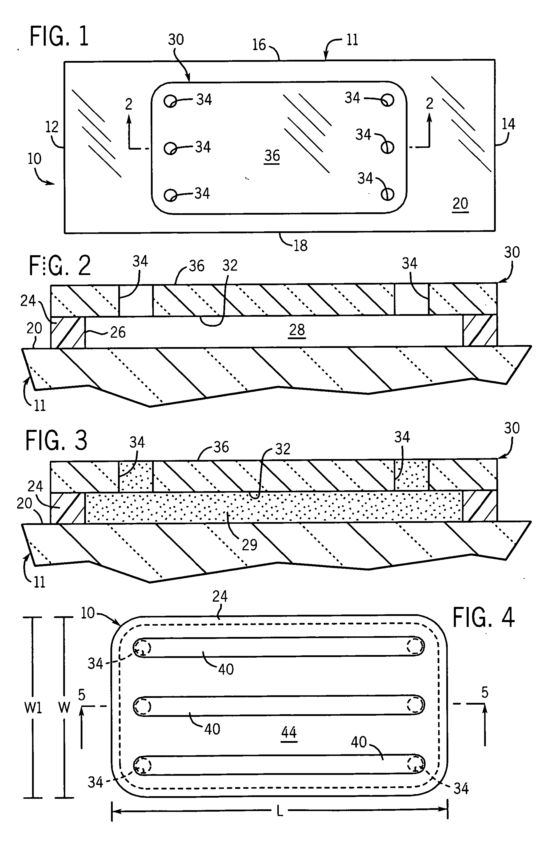
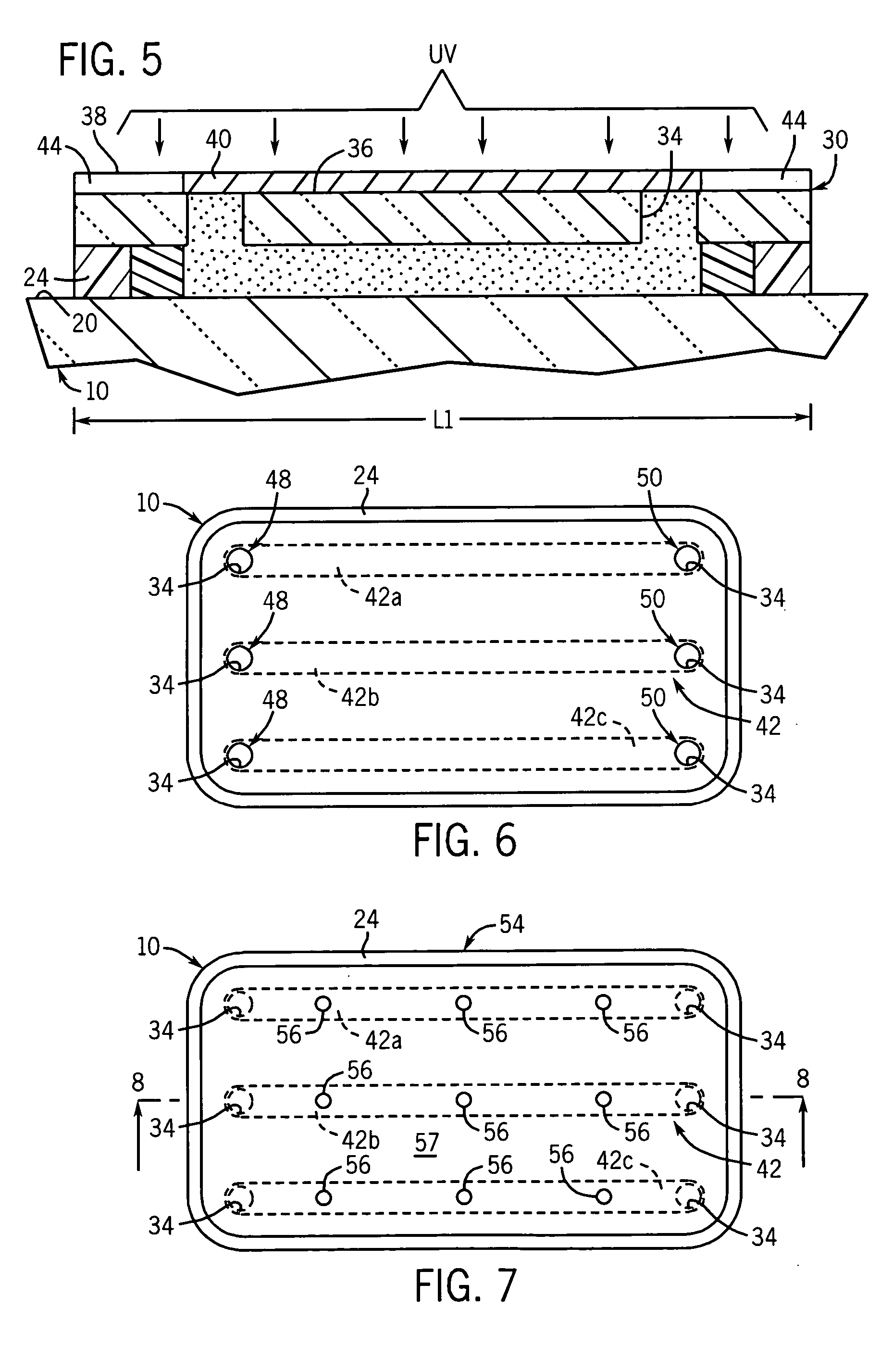
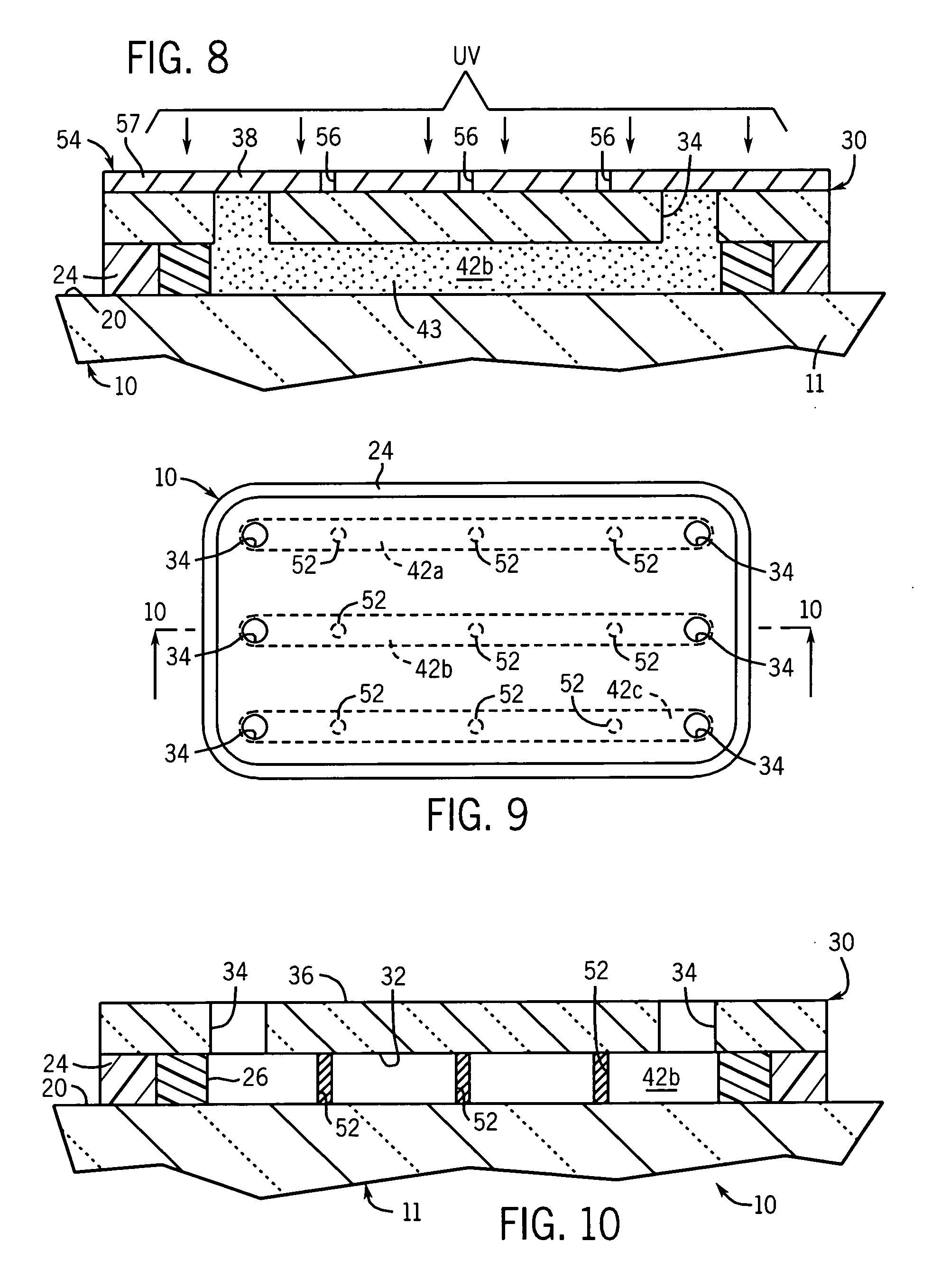
[0032] Referring to FIGS. 1 and 2, a microfluidic device defining the cell platform of the present invention and used to effectuate the methodology of the present invention is generally designated by the reference numeral 10. As hereinafter described, it is contemplated to fabricate a microfluidic device in a variety of manners including use of photopolymerizable solutions. It is noted, however, microfluidic device 10 may be fabricated from other materials without deviating from the scope of the present invention. Further, in order to achieve in situ fabrication of the specific components hereinafter described, liquid phase photopolymerization may be used, although the various channels within microfluidic device can be fabricated using other methods (e.g., micromolding).

[0033] By way of example, microfluidic device 10 includes a generally rectangular glass slide 11 defined by first and second ends 12 and 14, respectively; first and second edges 16 and 18, respectively; and upper fa...


PUM


Abstract

A platform and method for mimicking the environment within a cell is provided. The platform includes a microfluidic device defining a chamber. At least one hydrogel post is positioned within the chamber of the microfluidic device. Each hydrogel post defines a corresponding pore for receiving a first molecule therein. Second molecules are introduced into the pores of the hydrogel posts and the interactions between the first and second molecules are observed.

Description

REFERENCE TO GOVERNMENT GRANT [0001] This invention was made with United States government support awarded by the following agencies: DOD ARPA F 30602-00-2-0570. The United States has certain rights in this invention.FIELD OF THE INVENTION [0002] This invention relates generally to microfluidic devices, and in particular, to microfluidic-based cell mimic platform for biomolecular studies and a method of mimicking the environment within a cell utilizing the platform. BACKGROUND AND SUMMARY OF THE INVENTION [0003] The various events that occur inside a cell, such as metabolism and signal transduction, are orchestrated at the molecular level. For example, in signal transduction, a cascade of biomolecular interactions is initiated. These interactions include (but are not limited to) phosphorylation, binding and transportation of molecules. The effects of these interactions are often transmitted to the nucleus wherein the gene expression pattern is modified based on the signal. In metabo...

Claims


Application Information

Patent Timeline
IPC IPC(8): C12Q1/00C12M1/34
CPCB01L3/5027B01L2200/0668B01L2300/0822B01L2300/0877
Inventor BEEBE, DAVID J.MOORTHY, JAISREEBURGESS, RICHARD R.
Owner WISCONSIN ALUMNI RES FOUND
Why Eureka
Try Eureka