Plasma processing apparatus and method for controlling the same

Inactive Publication Date: 2006-06-01
HITACHI HIGH-TECH CORP
View PDF2 Cites 46 Cited by
  • Summary
  • Abstract
  • Description
  • Claims
  • Application Information

AI Technical Summary

Benefits of technology

[0034] According to the present invention, upon performing phase control of the voltage waveforms of the third RF power and the second RF power supplying bias to the processing substrate, the phase difference at each electrode radiating power to the plasma can be controlled with high accuracy, and as a result of controlling the ion energy colliding against the wall and the interaction between ion and wall, the

Problems solved by technology

However, according to the prior art, there are a means for detecting and a means for adjusting the phase difference of the RF between upper and lower biases, and though it is stated that the phase difference should preferably be controlled to 180 degrees, there is no disclosure on how to guarantee the achievement of the object by phase control.
The second drawback of the prior art is that even if the prior art method can be adopted to control the phase difference to 180 degrees, for example, it is not capable of guaranteeing that the phase difference of the voltages actually appearing at the upper and lower electrodes is 180 degrees.
Therefore, even if phase data is taken at each matching network of the upper and lower electrodes, the RF transmission paths that lead to the electrodes from the matching network vary, so there is no guarantee that the phase difference of the voltages generated at the electrodes is as controlled.
Another fact that influences the present problem is that the impedance of the RF transmission path leading to the earth seen from the upper electrode and the impedance of the RF transmission path leading to the earth seen from the lower electrode are not equal.
Further, since wafer processing is progressed near the lower electrode, the large amount of reaction products generated from the wafer causes the status of plasma near the lower electrode

Method used


Image

  • Plasma processing apparatus and method for controlling the same
  • Plasma processing apparatus and method for controlling the same
  • Plasma processing apparatus and method for controlling the same

Examples


Example

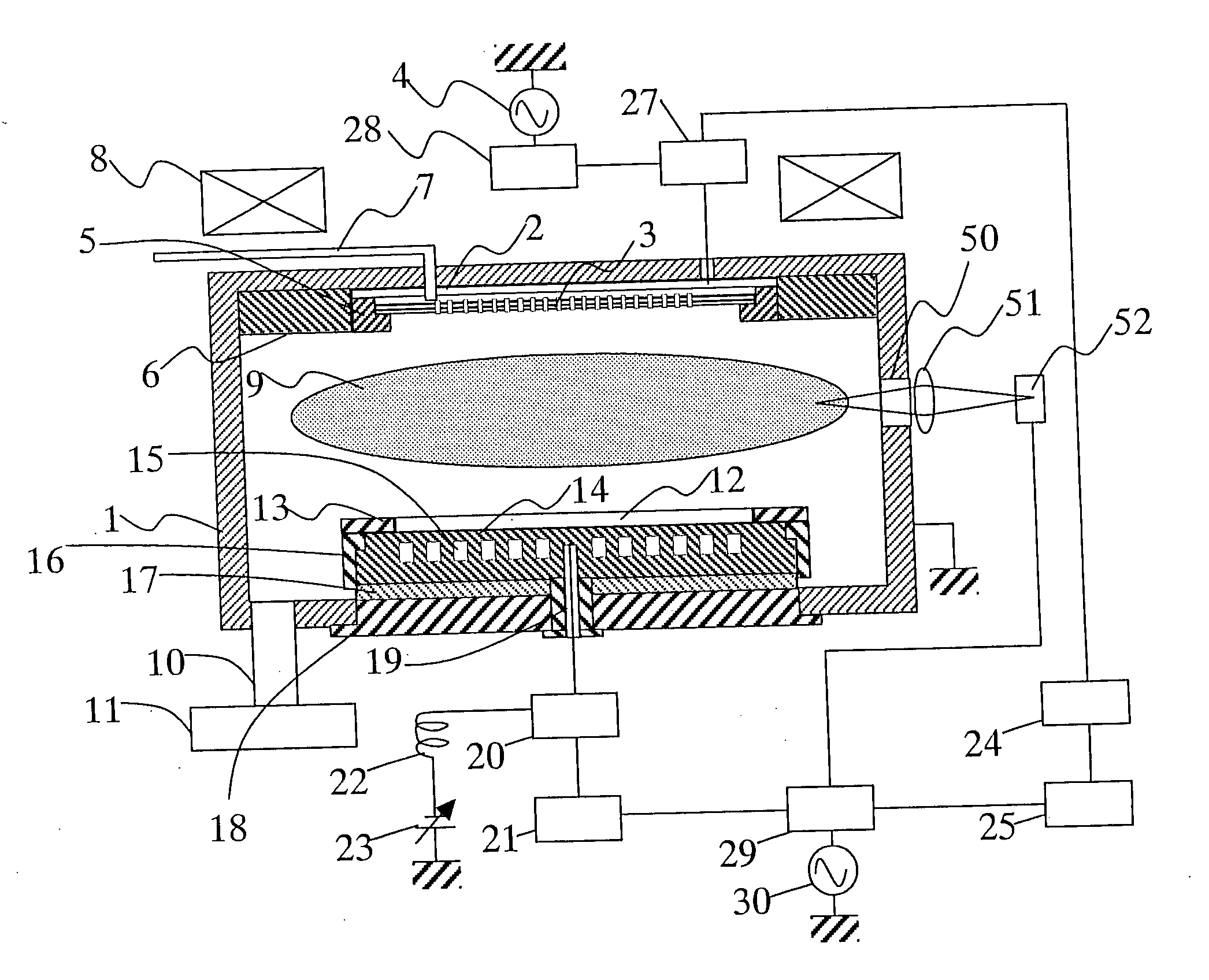
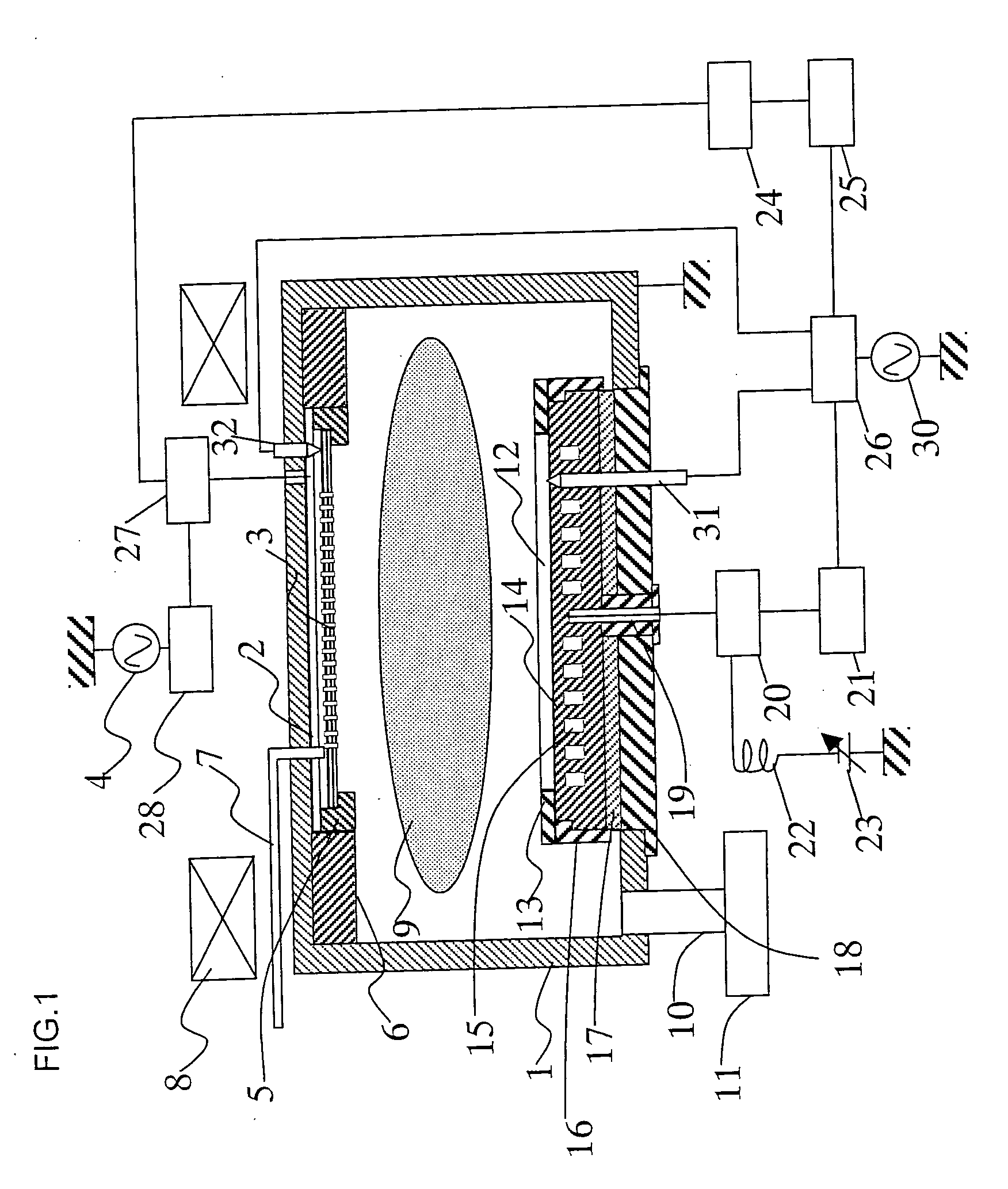
[0045] The overall structure of a plasma processing apparatus according to the present invention will now be described with reference to the schematic cross-sectional view of FIG. 1.

[0046] The plasma processing apparatus has a vacuum vessel 1 formed of conductive material such as aluminum, and in the vacuum vessel are attached an antenna 2 and a shower plate 3 via shower plate support flanges 5 and 6, respectively. The vacuum vessel 1 is grounded. Gas is supplied from the atmospheric side of the vessel through a process gas introduction pipe 7 to the space between the antenna 2 and the shower plate 3, and the gas is ejected into the vacuum vessel 1 through the many fine pores formed to the shower plate 3. Of course, the antenna 2 is formed of a conductive material, but the shower plate 3 can be formed of a conductive material, a dielectric material or a semiconductor material. When the shower plate 3 is formed of either conductive or semiconductor material, the shower plate 3 funct...


PUM


Abstract

The invention provides a plasma processing apparatus that realizes a most suitable inner environment of a vacuum vessel for each process. A plasma processing apparatus comprises a vacuum vessel 1, a first RF power supply 4, a second RF power supply 21, a third RF power supply 25, a first electrode 2 disposed within the vacuum vessel to which is supplied a mixture of a first RF voltage from the first RF power supply and a third RF voltage from the third RF power supply, a second electrode 14 disposed within the vacuum vessel to which is supplied a second RF voltage from the second RF power supply and having an upper surface mounting a sample 12, and a phase control unit 26 for controlling the phase difference of the second and third RF voltages, wherein the second and third RF voltages are of equal frequency, and the apparatus further comprises a first phase detecting means 32 for detecting the phase of the third RF voltage of the first electrode and a second phase detecting means 31 for detecting the phase of the second RF voltage of the second electrode, and based on the output of the first and second phase detecting means, controls the phase difference of the second and third RF voltages.

Description

[0001] The present application is based on and claims priority of Japanese patent application No. 2004-341723 filed on Nov. 26, 2004, the entire contents of which are hereby incorporated by reference. BACKGROUND OF THE INVENTION [0002] 1. Field of the Invention [0003] The present invention relates to an art for manufacturing semiconductor devices. Specifically, the present invention relates to a plasma processing apparatus and a method for controlling the plasma processing apparatus suitable for carrying out a plasma processing of a semiconductor wafer using plasma. [0004] 2. Description of the Related Art [0005] Along with the recent trend of large-scale integration of semiconductor devices, the circuit patterns have become finer and finer, and the demands for accurate dimension processing have become very strict. Further, the wafer diameter has become as large as 300 mm with the aim to reduce manufacturing costs of the semiconductor devices, so there are also demands for uniformiz...

Claims


Application Information

Patent Timeline
IPC IPC(8): H01L21/306C23F1/00C03C15/00
CPCC23F4/00H01J37/32165H01J37/32082
Inventor NISHIO, RYOJI
Owner HITACHI HIGH-TECH CORP
Why Eureka
Try Eureka