Substrate-supported process for manufacturing microfibrous fuel cells

Inactive Publication Date: 2006-06-08
MICROCELL CORP
View PDF27 Cites 13 Cited by
  • Summary
  • Abstract
  • Description
  • Claims
  • Application Information

AI Technical Summary

Benefits of technology

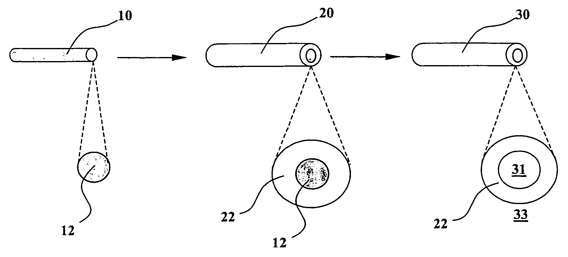
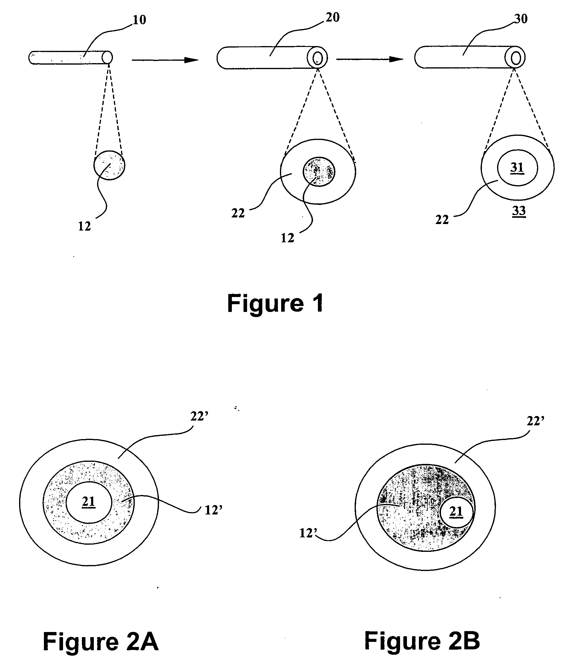
[0020] The solid-phase removable substrate material of the present invention provides a solid-phase substrate of sufficient mechanical strength for the membrane-forming material layer coated thereon, so that such membrane-forming material layer can withstand external forces during the manufacturing process, when the membrane wall is not yet solidified. Such solid-phase removable substrate material is subsequently removed to form a lumen allowing passage of fluid therethrough. Since the solid-phase removable substrate material is removed only after solidification of the membrane wall, such lumen is well protected against deformation during the manufacturing process. The hollow fibrous membrane separator formed by the method of the present invention therefore contains a clear fluid path with few or no flat spots.
[0031] The method described hereinabove significantly simplifies the manufacturing process for microfibrous fuel cells, which enables continuous and automated scale-up production of such microfibrous fuel cells.

Problems solved by technology

However, such conventionally methods depend on use of a liquid or a gas as a lumen-forming agent, which is a fluid and cannot provide sufficient support against deformation caused by external force during the manufacturing process.
Therefore, the hollow fibrous membrane separators formed by such methods may suffer from flat spots, which refers to blockage of the lumen or the fluid path within specific sections of the membrane separators, due to deleterious external force applied to the membrane separators before the membrane separator wall becomes fully solidified.
The co-extrusion process is very complicated, and the inner electrocatalyst and the hollow fibrous membrane layers formed by such process are also subject to significant deformation, due to the fact that such co-extrusion process provides little or not support to the newly-formed inner electrocatalyst and hollow fibrous membrane layers before complete solidification thereof.
Subsequent catalyzation of the hollow fibrous membrane separator is not only complicated, but also increases the risk of blocking the required fluid path within such hollow fibrous membrane separator during the catalyzation steps.

Method used


Image

  • Substrate-supported process for manufacturing microfibrous fuel cells
  • Substrate-supported process for manufacturing microfibrous fuel cells
  • Substrate-supported process for manufacturing microfibrous fuel cells

Examples


example 1

[0139] In the fabrication of the microfibrous fuel cell in this example, a 304-grade stainless steel wire having a diameter of 0.020″ was provided as the inner current collector.

[0140] A removable polymer layer was formed over the inner current collector by extruding onto such inner current collector a polyvinyl pyrrolidone (PVP) solution (Luvitec K60, 45 wt %, as supplied by BASF Corporation), followed by drying.

[0141] The extrusion process conditions for the PVP 60 were:

Line Speed:3 m / minExtrusion Temperature:ambient (approximately 72° F. / 22° C.)Extrusion Rate:0.54 ml / minExtrusion Die Orifice:0.053″Extrusion Tip:0.023″× 0.032″ hypo-tubeIR Dryer Length:1 mIR Dryer Set Point:425° C.

[0142] After drying, the fiber was collected on a spool. The cross-section of the fiber was examined under a microscope and measured with a micrometer, showing that such fiber has a PVP layer of approximately 50 to 60 microns and an outer diameter of approximately 600 to 617 microns.

[0143] A membrane...

example 2

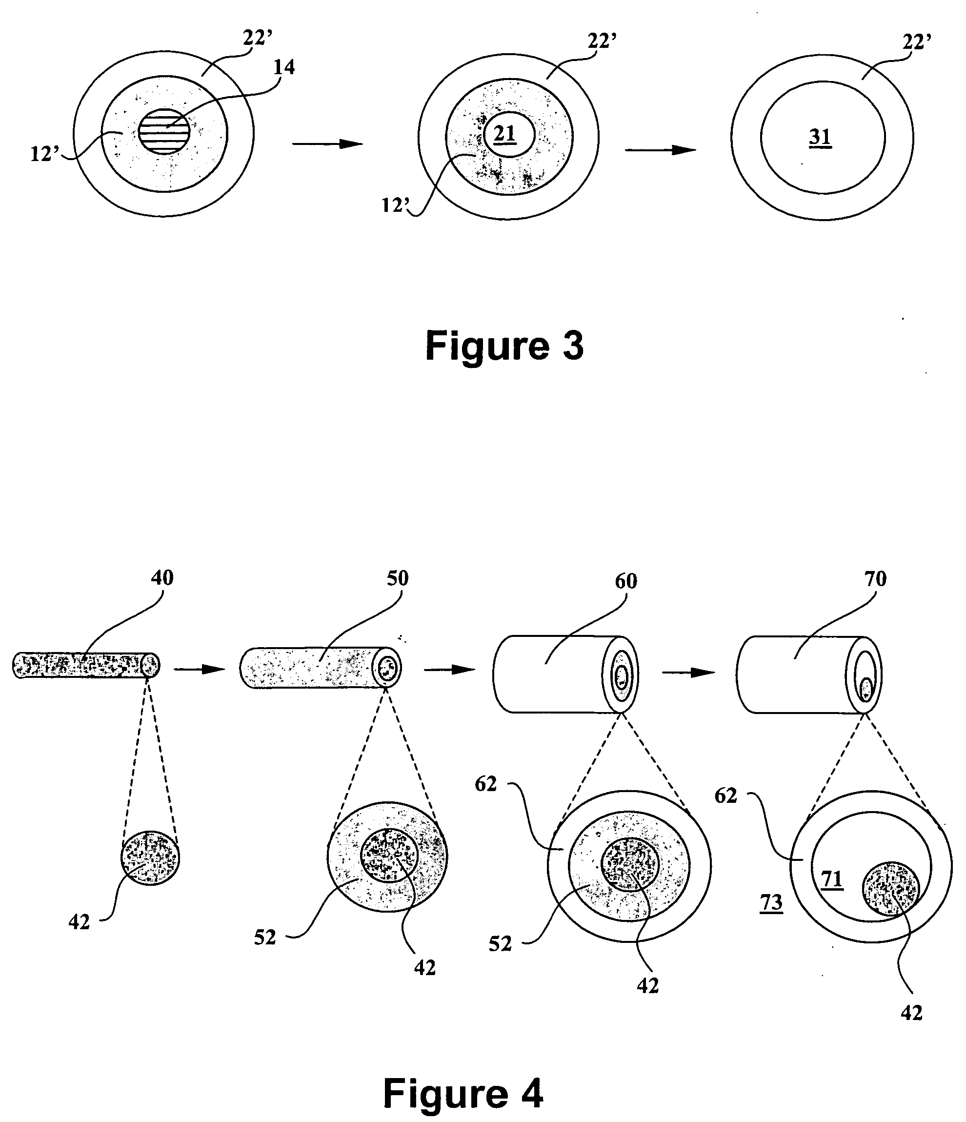
[0156] A hollow microfibrous Nafion membrane / inner current collector assembly was fabricated by a process similar to that described in Example 1, except that the removable substrate was consisted of two removable polymeric layers, including a first removable layer of PVP 60, as described hereinabove in Example 1, and a second removable layer of polyvinyl alcohol PVA (Elvanol, grade 70-62, from DuPont).

[0157] An aqueous solution of PVA was prepared by gradually dissolving the PVA polymer in hot water with stirring. The PVA concentration of such solution was 13 wt %, which gave sufficient viscosity for the extrusion process. To ensure complete drying of the PVA layer, a second infrared unit was put in line. Process conditions for the PVA extrusion were:

Line Speed:1 m / minExtrusion Temperature:ambient (approximately 72° F. / 22° C.)Extrusion Rate:0.23 ml / minExtrusion Die Orifice:0.034″Extrusion Tip:0.032″IR #1 Dryer Length:1 mIR #1 Dryer Set Point:425° C.

[0158] The thickness of the PVA...

example 3

[0161] A microfibrous fuel cell was prepared as follows:

[0162] A removable layer of polyvinyl pyrrolidone (PVP) was first formed by extruding a 45% Luvitec K60 PVP solution (supplied by BASF Corporation) around a titanium wire. An inner electrocatalyst layer was then applied onto the PVP-coated wire via ink extrusion. Two membrane-forming layers of concentrated 32 wt % Nafion solution were sequentially extruded over such inner electrocatalyst layer.

[0163] Specifically, the 32 wt % concentrated Nafion was obtained by evaporating a diluted Nafion solution that contained 20 wt % Nafion 1100EW (from Solution Technology, Inc.) in a mixture of alcohols and water. The concentrated Nafion solution had a viscosity of 890 poises, as measured by a rotational viscometer (Brookfield LVT model) with a #4 spindle at 6 rpm.

[0164] The catalyst ink used for forming the inner electrocatalyst layer was prepared by blending:

Material% weightPlatinum black (HiSpec 1000 from Alfa Aesar)16.0Deionized w...


PUM

PropertyMeasurementUnit
Temperatureaaaaaaaaaa

Abstract

The present invention relates to a substrate-supported process for continuous and automated manufacturing of microfibrous fuel cells and other electrochemical cells. Specifically, a removable substrate layer is formed around an inner current collector, followed by sequentially coating multiple structure layers, such as the inner catalyst layer, the membrane separator, and the outer catalyst layer, over such removable substrate layer, and subsequent removing such removable substrate layer, so as to form a lumen around the inner current collector, to allow passage of fluid therethrough. The removable substrate layer preferably comprises a water-soluble polymer, such as polyvinyl pyrrolidone (PVP), polyvinyl alcohol (PVA), or polyethylene glycol (PEG).

Description

CROSS-REFERENCE TO RELATED APPLICATIONS [0001] This application is a divisional of U.S. patent application Ser. No. 10 / 744,203, filed on Dec. 23, 2003, which in turn claims the benefit of priority to U.S. Provisional Patent Application No. 60 / 436,072, filed on Dec. 23, 2002 in the names of Ray R. Eshraghi et al. for “SUBSTRATE-SUPPORTED PROCESS FOR MANUFACTURING MICROFIBROUS FUEL CELLS” and the benefit of priority to U.S. Provisional Patent Application No. 60 / 457,903, filed on Mar. 27, 2003 in the names of Ray R. Eshraghi et al. for “PROCESS FOR MANUFACTURING HOLLOW FIBERS.” The disclosures of all of said prior filed U.S. applications are hereby incorporated herein by reference in their respective entireties, for all purposes.GOVERNMENT INTEREST [0002] The U.S. government may have rights in the present invention, pursuant to Grant No. 70NANB1H3039 awarded by the Advanced Technology Program (ATP) of National Institute of Science and Technology (NIST).BACKGROUND OF THE INVENTION [0003...

Claims


Application Information

Patent Timeline
IPC IPC(8): B29C41/24B05D5/12B29C47/02H01M4/86H01M4/88H01M4/90H01M4/92H01M8/02H01M8/10H01M8/18H01M8/24H01M10/28H01M50/406H01M50/469
CPCH01M2/145H01M2/18H01M4/8605H01M4/8626H01M4/8807H01M4/8814H01M4/8828H01M4/8864H01M4/90H01M4/9016H01M4/921H01M8/004H01M8/023H01M8/0239H01M8/0252H01M8/1004H01M8/1006H01M8/1023H01M8/1025H01M8/1027H01M8/1032H01M8/1039H01M8/106H01M8/1062H01M8/1065H01M8/1097H01M8/18H01M8/241H01M10/28H01M2008/1095Y02E60/124Y02E60/521Y02E60/528Y02E60/50Y02P70/50Y02E60/10H01M50/406H01M50/469B29C48/15H01M8/2404
Inventor ESHRAGHI, RAY R.KETTERER, MARTIN E.SI, YONGCHAO
Owner MICROCELL CORP
Why Eureka
Try Eureka