
Recording medium

a technology of recording medium and recording signal, which is applied in the field of recording medium, can solve the problems of difficult high densification and inability to obtain sufficient recording characteristics of optical recording medium, and achieve the effects of wide recording power range, good recording signal characteristics, and high densification of information

Active Publication Date: 2006-06-08
CMC MAGNETICS CORPORATION
View PDF6 Cites 23 Cited by
  • Summary
  • Abstract
  • Description
  • Claims
  • Application Information

AI Technical Summary

Benefits of technology

[0036] According to the present invention, it is possible to obtain a recording medium which can be adapted for high densification of information. Particularly, it is possible to obtain a write-once-read-many optical recording medium having a wide recording power range wherein good recording signal characteristics can be obtained.

Problems solved by technology

Namely, it was impossible to obtain sufficient recording characteristics with an optical recording medium wherein a single substance of an oxide or nitride decomposable under heating by irradiation of a laser beam, was employed for a recording layer.
Namely, it was found that although it was possible to take a sufficiently large amplitude of recording signals, the recording power range (the power margin) wherein good recording signal characteristics can be obtained, was very narrow, and with a recording medium utilizing decomposition of the recording layer made of single substance, high densification was difficult.

Method used


Image

  • Recording medium
  • Recording medium
  • Recording medium

Examples


example 1

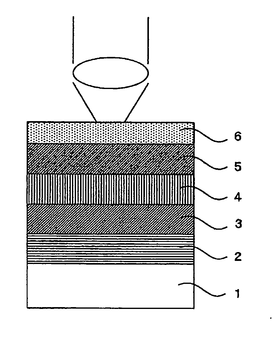
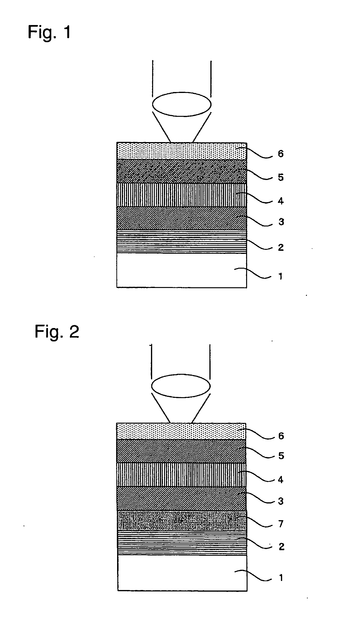
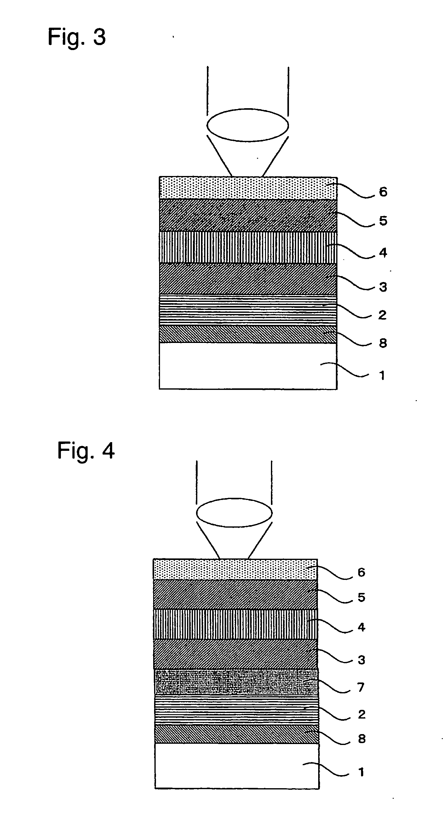
[0183] As an Example of the embodiment of the present invention, an optical recording medium having a structure shown in FIG. 4 was prepared. For the substrate 1, a disk-shaped polycarbonate resin having a thickness of 1.1 mm and a diameter of 120 mm was employed. For the underlayer 8, Ta was employed. For the reflective layer 2, an alloy of Ag—Cu—Nd was employed. For the diffusion preventing layer 7, Ge—Cr—N was employed. For the protective layers 3 and 5, a mixture comprising ZnS—SiO2 was employed. For the recording layer 4, tin nitride (Sn nitride) was used as the substance A, and tantalum nitride (Ta nitride) was used as the substance B.

[0184] With respect to the light transmission layer 6, 2.5 g of a non-cured (non-polymerized) acrylate ultra-violet-curable agent having a viscosity of 3,000 mPa·s was dropped at the center portion of the protective layer and spin-coated at a rotational speed of 1,500 rpm for 6 seconds and then irradiated with ultraviolet rays for curing (polyme...

example 2

[0215] Sputtering target: Sn and Ta (co-sputtering)

[0216] Sputtering power for Sn: DC 210 W [0217] Ta: RF 500 W

[0218] Ar+N2 gas pressure: 0.35 Pa

[0219] N2 / (Ar+N2) flow rate ratio: 0.75

[0220] Thickness: 15 nm

example 3

[0221] Sputtering target: Sn and Ta (co-sputtering)

[0222] Sputtering power for Sn: DC 210 W [0223] Ta: RF 700 W

[0224] Ar+N2 gas pressure: 0.35 Pa

[0225] N2 / (Ar+N2) flow rate ratio: 0.75

[0226] Thickness: 15 nm


PUM

PropertyMeasurementUnit
Temperatureaaaaaaaaaa
Thicknessaaaaaaaaaa
Thicknessaaaaaaaaaa

Abstract

The main object of the present invention is to provide a recording medium which makes high densification of information possible, particularly a write-once-read-many optical recording medium having good recording signal characteristics to a wide range of recording powers. The present invention is one to accomplish the above object by providing a recording medium having a recording layer, whereby recording is carried out by heating the recording layer, characterized in that the recording layer contains a substance A which decomposes at a temperature which the recording layer reaches when heated for recording, and a substance B which does not undergo a chemical reaction or phase change at a temperature which the recording layer reaches when heated for recording.

Description

TECHNICAL FIELD [0001] The present invention relates to a recording medium whereby recording is carried out by heating a recording layer. Particularly, such a recording medium is a write-once-read-many optical recording medium whereby recording is carried out by laser irradiation, characterized in that the recording layer contains a substance which decomposes at a temperature which the recording layer reaches when heated by the laser, and a substance which does not undergo a change such as a chemical reaction at such a temperature. BACKGROUND ART [0002] As recording media for recording information such as writings, sounds or images, recording media have heretofore been known which employ e.g. a phase change material made of a magnetic material, a magnetooptical material, an organic dye material or an inorganic material, for a recording layer. [0003] Such recording media are designed so that a physical parameter of the recording layer, such as the refractive index, electrical resista...

Claims


Application Information

Patent Timeline
IPC IPC(8): G11B7/24B41M5/26G11B7/0045G11B7/243G11B7/257G11B7/258
CPCG11B7/0045G11B7/00451G11B7/00452Y10T428/21G11B7/257G11B7/258G11B7/243
Inventor KIYONO, KENJIROU
Owner CMC MAGNETICS CORPORATION
Learn More