Nuclear reactor feed-water system

a technology of nuclear reactors and feedwater, which is applied in the direction of water feed control, greenhouse gas reduction, nuclear elements, etc., can solve the problems of not obtaining predetermined reactor water levels, difficult to maintain set water levels, and difficulty in maintaining a suitable set water level of reactor water, so as to maintain a stable reactor water level and suppress power consumption

Inactive Publication Date: 2006-06-08
KK TOSHIBA
View PDF3 Cites 10 Cited by
  • Summary
  • Abstract
  • Description
  • Claims
  • Application Information

AI Technical Summary

Benefits of technology

[0017] The present invention was conceived in consideration of the above matters encountered in the prior art and an object of the present invention is to provide a nuclear reactor feed-water system capable of keeping a stable react

Problems solved by technology

However, there is a fear that, by a desensitizing zone of the fed-water regulation valve 10, the feed-water flow rate causes hunching phenomenon and variation in the reactor water level, so that it becomes difficult to maintain a suitable set water level of the reacto

Method used


Image

  • Nuclear reactor feed-water system
  • Nuclear reactor feed-water system
  • Nuclear reactor feed-water system

Examples


first embodiment

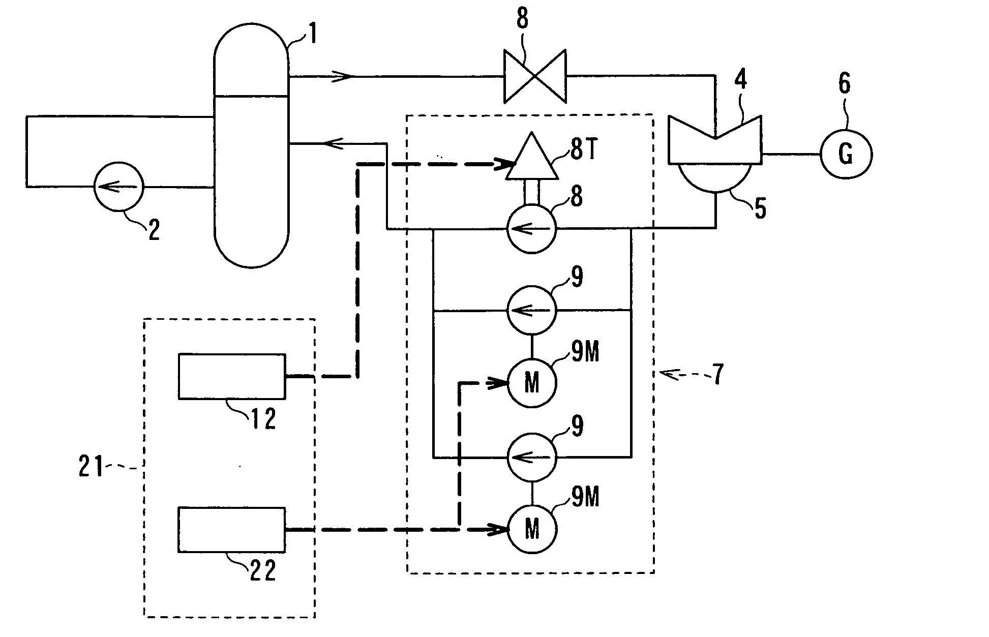
[0047] A reactor feed-water system according to the first embodiment will be described with reference to FIGS. 1 to 3.

[0048] The nuclear reactor feed-water system of this first embodiment basically differs from the conventional technology mentioned hereinbefore in the point that the feed-water pump drive motor 9M is driven by a semiconductor power conversion apparatus, for generating variable frequency and variable voltage, in place of the reactor feed-water regulation valve 10 in the conventional structure.

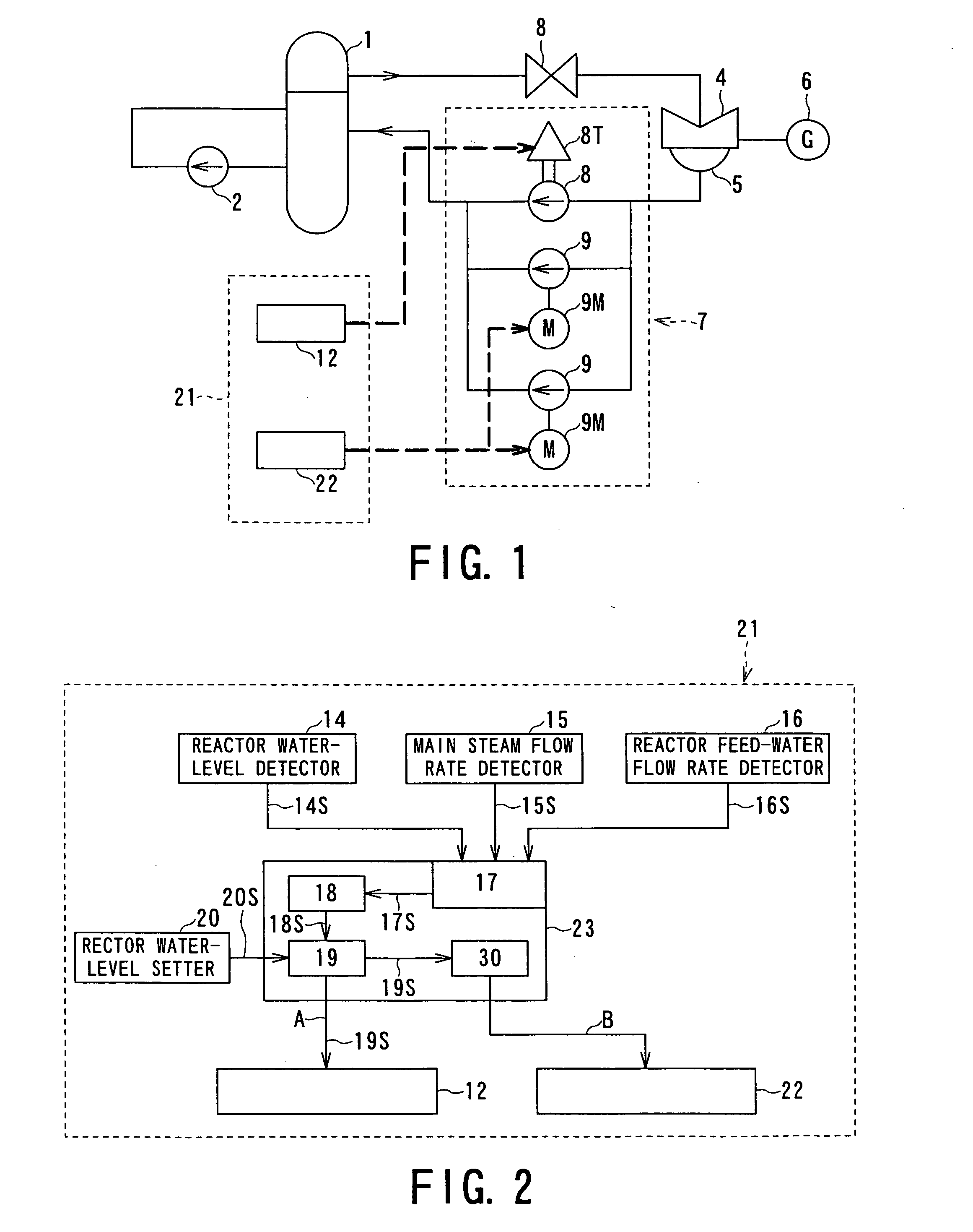
[0049] With reference to FIG. 1, a reactor feed-water pump control unit 21 is newly disposed in place of the conventional reactor feed-water pump control unit 11, and a semiconductor power conversion circuit 22 including an inverter is also disposed in place of the feed-water regulation valve control circuit 13 so as to make variable the output frequency and output voltage by a trigger signal given to a switching device constituting the inverter. The details of such semiconduct...

second embodiment

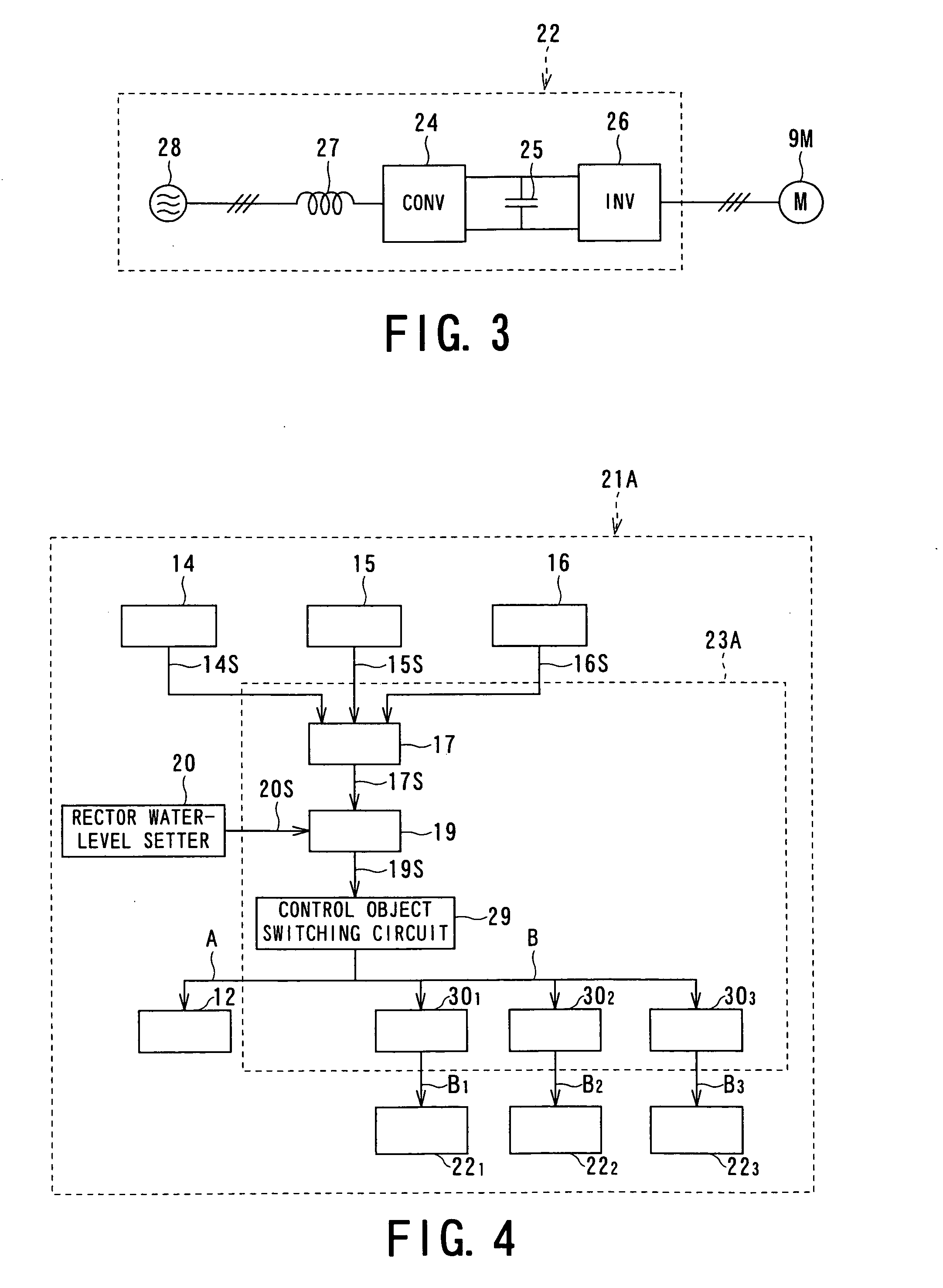
[0059]FIG. 4 shows a block diagram representing the nuclear reactor feed-water pump control unit according to the second embodiment of the present invention.

[0060] The embodiment relates to the nuclear reactor feed-water pump control unit provided with a plurality of objects to be controlled (three, for example), and a control object switching circuit is additionally disposed in the control-operation circuit 23A, which is operated as a master control unit to carry out total control without disposed a plurality of units corresponding to the motor drive feed-water pumps 9. Further, in this and following embodiments, the three-function / single-function change-over switch is eliminated for the sake of easy explanation.

[0061] With reference to FIG. 4, reference numeral 21A denotes a nuclear reactor feed-water pump control unit, and reference numeral 29 denotes a control object switching circuit acting to select the motor driven feed-water pump 9 or turbine drive feed-water pump speed co...

third embodiment

[0069]FIG. 5 shows a block diagram representing the nuclear reactor feed-water pump control unit according to the third embodiment of the present invention.

[0070] With reference to FIG. 5, reference numeral 21B denotes a nuclear reactor feed-water pump control unit according to this third embodiment, in which the turbine drive feed-water pump speed control circuit 12 is eliminated. In the third embodiment, a by-pass conduit or line 32 provided with a by-pass valve 31 is connected between the inlet side and the outlet side of the motor drive feed-water pump 9 in the reactor feed-water pump control unit in the above first or second embodiment. In the controlling of the feed-water drive motor 9M utilizing the semiconductor power conversion circuit 22, if it is difficult to ensure the minimal flow rate in a low speed area at the driving time, the by-pass valve 31 of the by-pass line 32 could be opened only in the area to achieve a certain degree of speed at the driving operation statin...


PUM


Abstract

In a reactor feed-water system in which water is fed to a reactor pressure vessel by at least one reactor feed-water pump, a driving power for a feed-water pump drive motor is supplied from a semiconductor power conversion circuit adopting a self-excitation switching device; a reactor water-level detection value, a main steam flow rate detection value and a rector feed-water flow rate detection value are calculated by adding or subtracting these values; and a comparison result between the result of the calculation and a reactor water-level setting signal is given, as current command value to an inverter, to the inverter of the semiconductor power conversion circuit, thereby controlling the revolution number and torque of the feed-water pump drive motor, thus controlling the reactor feed-water flow rate.

Description

BACKGROUND OF THE INVENTION [0001] 1. Field of The Invention [0002] The present invention relates to a nuclear reactor feed-water system of a nuclear power plant, and more particularly, to a nuclear reactor feed-water system utilizing a semiconductor power conversion circuit as a power source of a feed-water pump drive motor. [0003] 2. Related Art [0004] A known nuclear reactor feed-water system adopted for an existing nuclear power plant will be first explained with reference to FIGS. 11 and 12. [0005]FIG. 11 is a schematic diagram of a nuclear reactor feed-water system utilized in a known technology, and FIG. 12 is a structural block diagram of a reactor feed-water pump control device. [0006] With reference to FIG. 11, the reference numeral 1 denotes a pressure vessel of a nuclear reactor and the reference numeral 2 denotes a re-circulation pump. A main steam generated in the pressure vessel 1 is fed to a steam turbine 4 through a main steam stop valve 3 and a steam control valve,...

Claims


Application Information

Patent Timeline
IPC IPC(8): G21C19/28
CPCF04D7/08F04D15/0066F22B35/004F22D5/00F22D5/26G21C19/28G21Y2002/201G21Y2002/204G21Y2002/207G21Y2002/304G21Y2004/30Y02E30/30
Inventor TOMIKI, HIROAKIASAKA, TAKEO
Owner KK TOSHIBA
Why Eureka
Try Eureka