
Mark forming method for moving body and moving body having mark

a technology of moving body and marking, applied in the field of marking forming method for moving body and moving body having mark, can solve the problems of difficulty in controlling image position difference, high accuracy, specific teaching of forming mark method, etc., and achieves the effect of small stretching, high accuracy, and no decrease in the tensile strength of the moving body

Inactive Publication Date: 2006-06-08
RICOH KK
View PDF4 Cites 29 Cited by
  • Summary
  • Abstract
  • Description
  • Claims
  • Application Information

AI Technical Summary

Benefits of technology

[0037] It is a general object of the present invention to provide a mark forming method for a moving body and a moving body having a mark, in which a moving state of the moving body such as a carrying belt in an image forming apparatus can be obtained accurately and moving speed unevenness of the moving body can be reduced without having damage or occurrence of a crack in the moving body and without generating a leakage current even when the moving body is exposed in a strong electric field.

Problems solved by technology

Consequently, it is difficult to control a position difference of the image on the transfer material carried by the rotating movement unit with high accuracy.
The above conventional technologies do not specifically teach a method of forming marks on the belt surface, and do not make problems occurring during an actual use clear.
However, when the holes are formed, tensile strength of the hole forming parts is extremely decreased and stretching frequently occurs, compared with the other parts.
Consequently, a correct belt carrying state cannot be obtained, a stress is concentrated on and a crack occurs in the hole forming parts, and there is danger of the belt breaking.
In addition, when the marks formed by the holes or reflection marks each formed by a metal reflection film are used, a leakage current occurs between the photoconductor body and the intermediate transfer belt to which high electric charge is applied.
Therefore, a bad influence is given to the transfer process, and this may cause a breakdown of the apparatus.
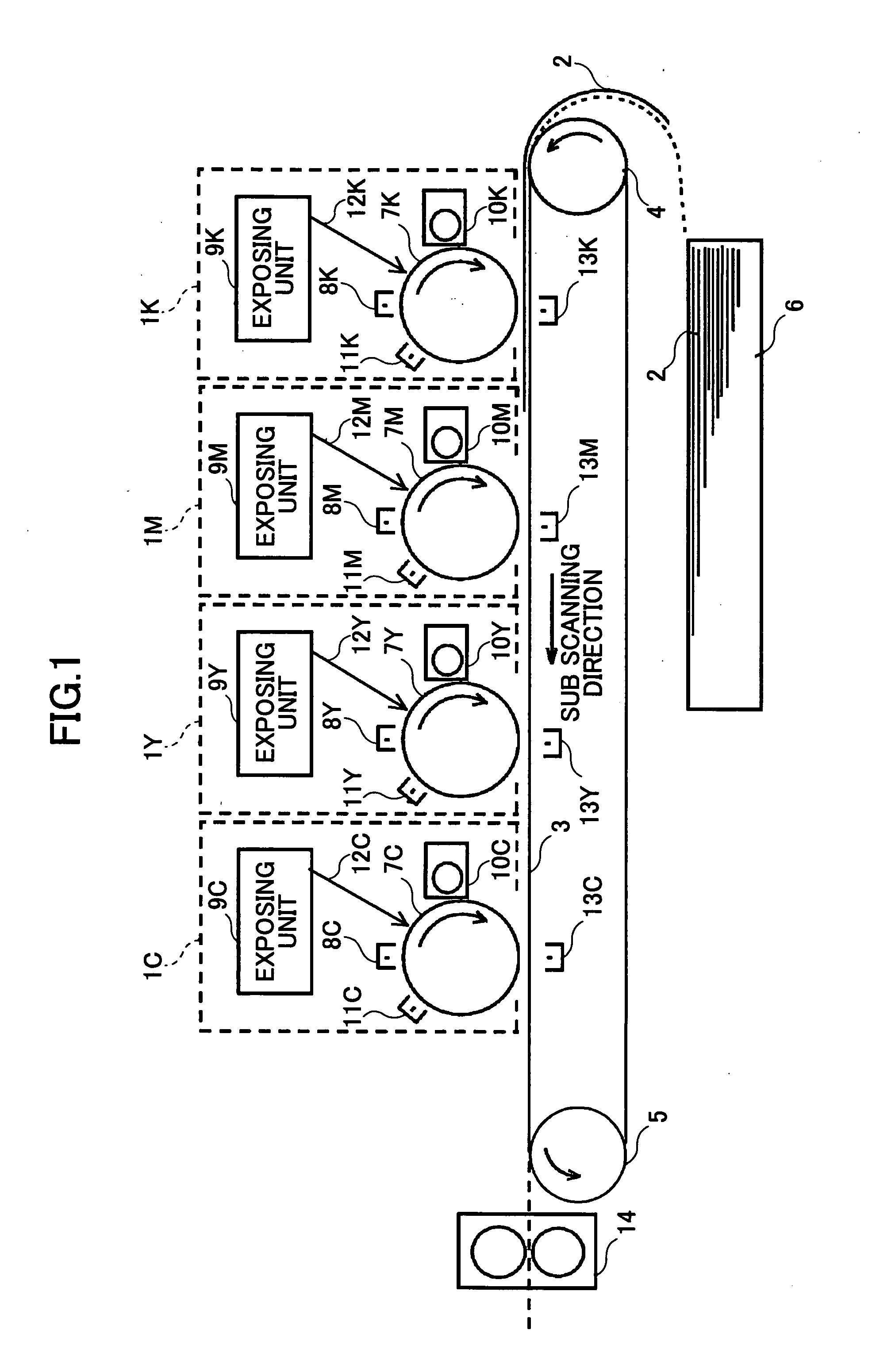
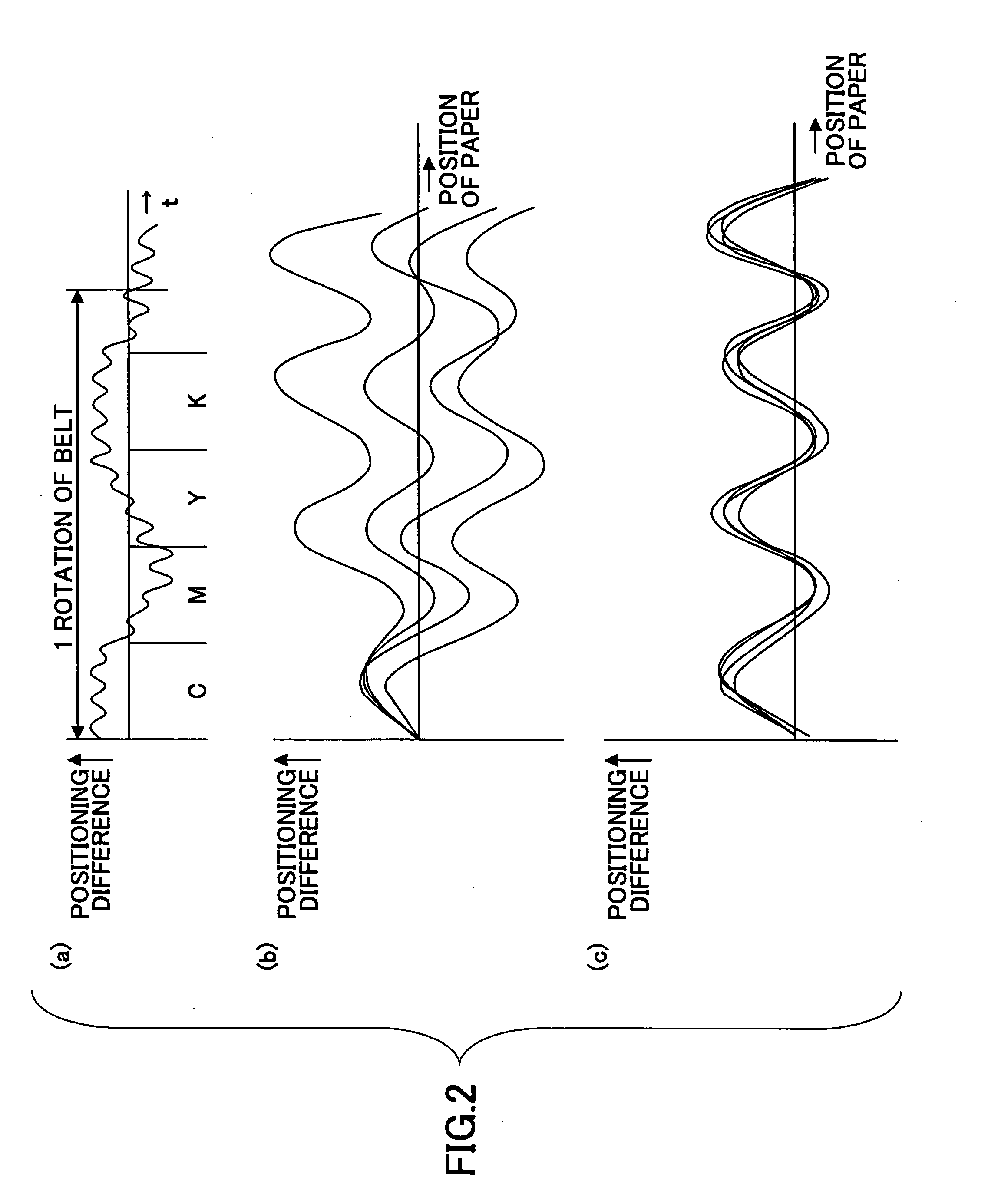
Consequently, there is a problem in that images are not registered at the position where the images should be registered and displacement among colors occurs.
In an output image in which images are registered during the speed change of the belt carrying unit, positions of colors do not match as shown in FIG. 2(b); therefore, image quality of the output image is deteriorated, that is, displacement of colors and a color change occur.
However, in the explanation of the conventional technology, a suitable method of forming the marks on the carrying belt is not described and problems to be solved at the time of actual usage are also not described.
The following problems are shown when reflectance control of a metal material layer is executed by a laser beam process.
(1) An adhesive under the metal material layer is damaged by heat at the time of laser beam processing.
(2) It is difficult to form a pattern with high accuracy due to occurrence of enlarging the pattern part caused by thermal conduction of metal at the time of laser beam processing.
(3) Even when a protecting layer exists, there is a possibility that current leakage occurs from ends and a crack of the protecting layer.

Method used


Image

  • Mark forming method for moving body and moving body having mark
  • Mark forming method for moving body and moving body having mark
  • Mark forming method for moving body and moving body having mark

Examples


first embodiment

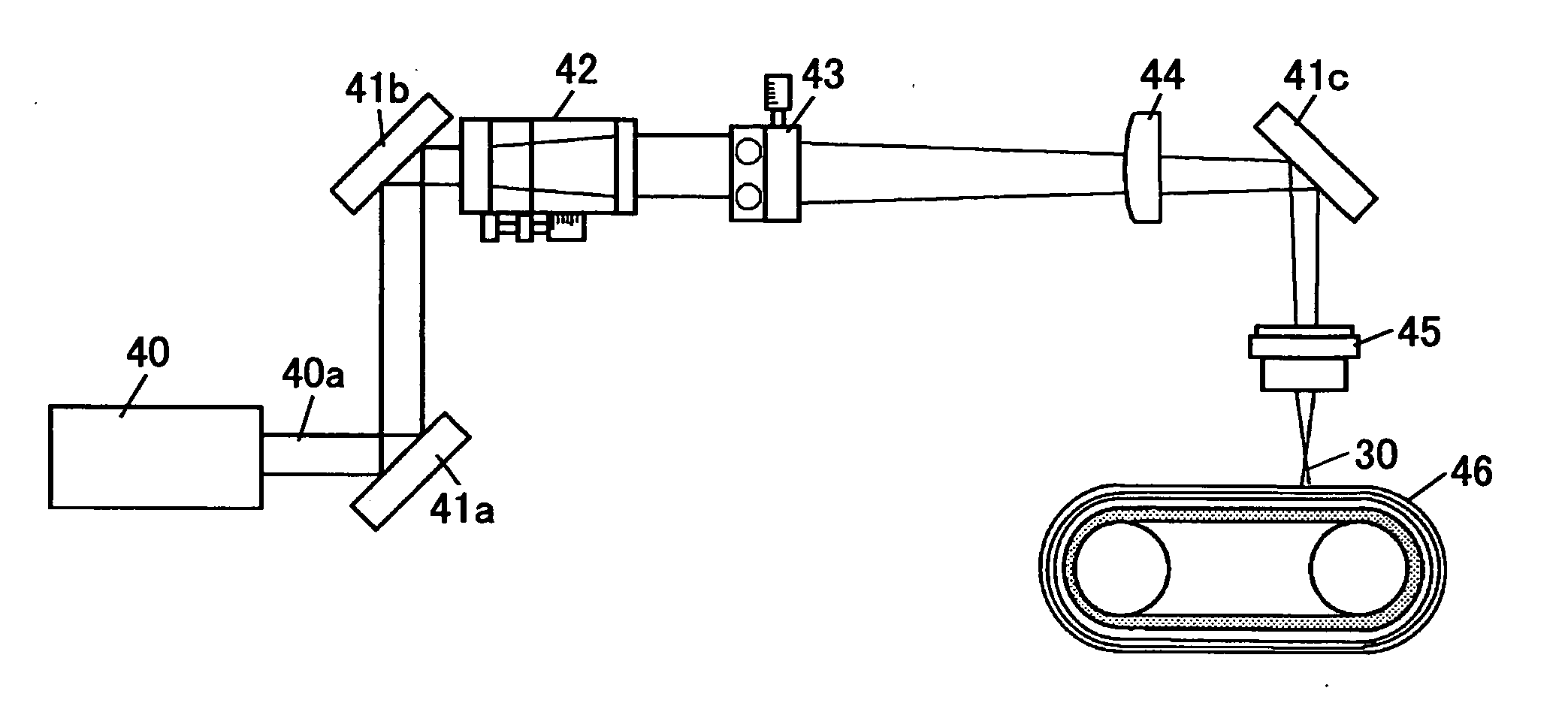
[0087] Again referring to FIG. 4, and further, referring to FIG. 5, a first embodiment of the present invention is explained. As mentioned above, FIG. 4 is a schematic diagram explaining the basic principle of forming a mark. FIG. 5 is a schematic diagram of a laser beam processing device.

[0088] First, the basic principle is explained in more detail. A dispersion material, whose laser beam for processing (30a and 30b) absorbing property is high, for example, titanium oxide particles, is dispersed on a PET resin being a substrate material, and with this, a substrate material layer 32 is formed. The substrate material layer 32 is disposed on a surface of a moving body 31 which is made of, for example, a resin such as a PI (polyimide) resin, a PET (polyethylene terephthalate) resin, and a PVDF (polyvinylidene fluoride) resin, or a metal material such as stainless steel. At this time, the substrate material layer 32 disposed on the surface of the moving body 31 is made of a material wh...

second embodiment

[0097] Referring to FIG. 6, a second embodiment of the present invention is explained. FIG. 6 is a schematic diagram explaining a mark forming method according to the second embodiment of the present invention.

[0098] In the second embodiment, on the substrate material layer 32 formed by dispersing, as in the first embodiment, such as titanium oxide particles on a PET resin, a transparent film 35 made of a material such as a PET resin being transparent for light wavelengths for processing and detecting is disposed. The substrate material and the dispersion material inside the substrate material layer 32 are transformed by a laser beam, for example, an ultraviolet light laser beam, by the same operation as in the first embodiment. In the second embodiment, forming and detecting the marks 35 are executed by the ultraviolet light laser beam transmitting through the transparent film 35. Therefore, the movement of the moving body 31 can be detected by the scattering amount of light for d...

third embodiment

[0103] Referring to FIG. 7, a third embodiment of the present embodiment is explained. FIG. 7 is a schematic diagram explaining a mark forming method according to the third embodiment of the present invention.

[0104] In the third embodiment, a reflection film 37 for a mark detecting sensor is disposed on the lower surface of the substrate material layer 32. At this time, the thinner the substrate material layer 32 is, the greater the effect is. The scattering strength in the substrate material layer 32 is made greater by the reflection film 37.

[0105] Like in the first and second embodiments, positions where the laser beams 30a and 30b are irradiated are transformed in the substrate material layer 32. When the transformed positions of the substrate material layer 32 are detected by an optical sensor, the scattering strength can be increased by disposing the reflection film 37. For example, the marks 33 can be detected by low output light, and with this, the SNR (signal to noise rati...


PUM


Abstract

A mark forming method for a moving body is disclosed. The method includes the steps of forming a second material layer, which scatters second wavelength light by being dispersed a first material that has a light absorbing property for first wavelength light therein, on a moving body; irradiating the first wavelength light on a part of the second material layer, making the first material at the part absorb the first wavelength light, and changing a scattering property of the part of the second material layer; and forming a mark whose scattering property for the second wavelength light is different in the part.

Description

BACKGROUND OF THE INVENTION [0001] 1. Field of the Invention [0002] The present invention generally relates to a mark (pattern) forming method for a moving body by using a laser beam with high accuracy and a moving body having a highly accurate mark; and in detail, relates to a rotating body having a mark for an image forming apparatus such as a photoconductor belt, a transfer belt, a paper carrying belt, a photoconductor drum, a transfer drum, and so on in an image forming apparatus such as a copying machine, a printer, and a facsimile. The present invention can be also applied to a positioning sensor and a pattern forming method. [0003] 2. Description of the Related Art [0004] In an image forming apparatus which provides rotating bodies for forming an image such as a photoconductor belt and an intermediate transfer belt, in order to accurately align an image on a transfer material carried by a rotating movement unit of the rotating body, it is required that a moving amount and a m...

Claims


Application Information

Patent Timeline
IPC IPC(8): G03G15/00
CPCG03G15/0131G03G15/5008G03G2215/00075G03G2215/0119G03G2215/0158
Inventor YAMADA, YASUFUMIKUDO, KOICHI
Owner RICOH KK
Learn More