System and method for regulating a load by utilizing pulse width modulation

a pulse width modulation and load technology, applied in the field of load regulation, can solve the problems of affecting the accuracy of current detection, wasting power and heat generated by resistors, and affecting real-time monitoring and controlling systems, so as to effectively adjust the working frequency and the supplied voltage of the load, and prevent the instability situation. , the effect of efficiently controlling the dissipation of heat generated

Inactive Publication Date: 2006-06-15
AOPEN
View PDF7 Cites 25 Cited by
  • Summary
  • Abstract
  • Description
  • Claims
  • Application Information

AI Technical Summary

Benefits of technology

[0008] It is another object of the present invention to provide the system and method for detecting the variation of the load current, which is independent on the operating system, thereby preventing the instability situations.
[0009] It is a further object of the present invention to dynamically and effectively adjust the working frequency and the supplied voltage of the load.
[0010] A further object of the present invention is to efficiently control the dissipation of the heat generated from the load of an electronic circuit.

Problems solved by technology

However, this scheme has some disadvantages.
Firstly, the accuracy of the current detection would be probably affected by the inaccuracy of the resistor itself, and by the environmental factors, such as temperature variation.
Secondly, the resistor wastefully consumes power and generates heat, especially when the current becomes large.
Unfortunately, the thermistor usually responds slowly, and therefore a real-time monitoring and controlling the system becomes difficult. FIG. 1 shows the relationship between the rotational (or spin) speed of the fan and the detected CPU temperature.
The detection by using such API possesses drawbacks existing in general software programs in that the operations sometimes cause delay, hang, or even crash, not to say such API is not supported by every system.

Method used


Image

  • System and method for regulating a load by utilizing pulse width modulation
  • System and method for regulating a load by utilizing pulse width modulation
  • System and method for regulating a load by utilizing pulse width modulation

Examples


Embodiment Construction

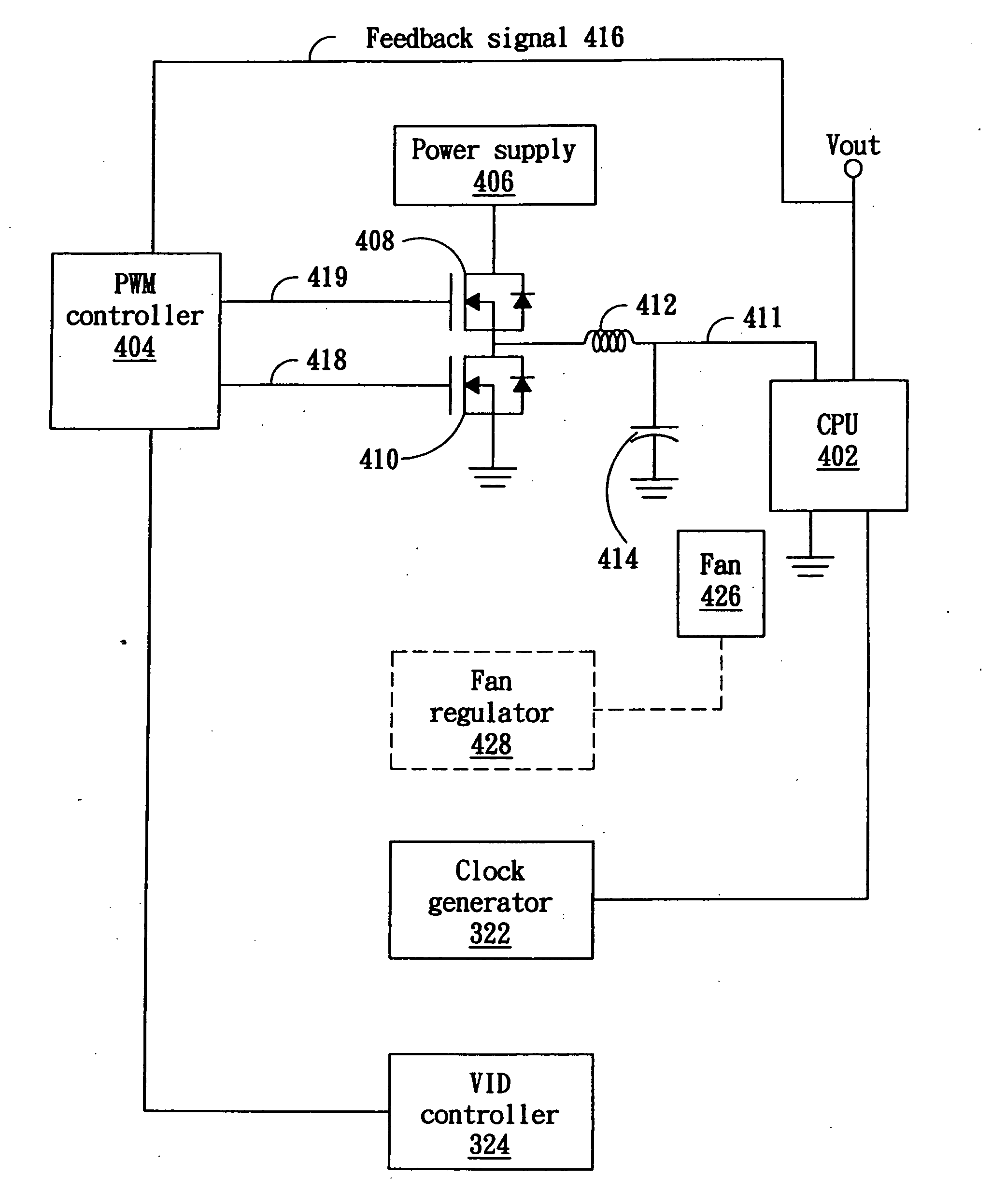
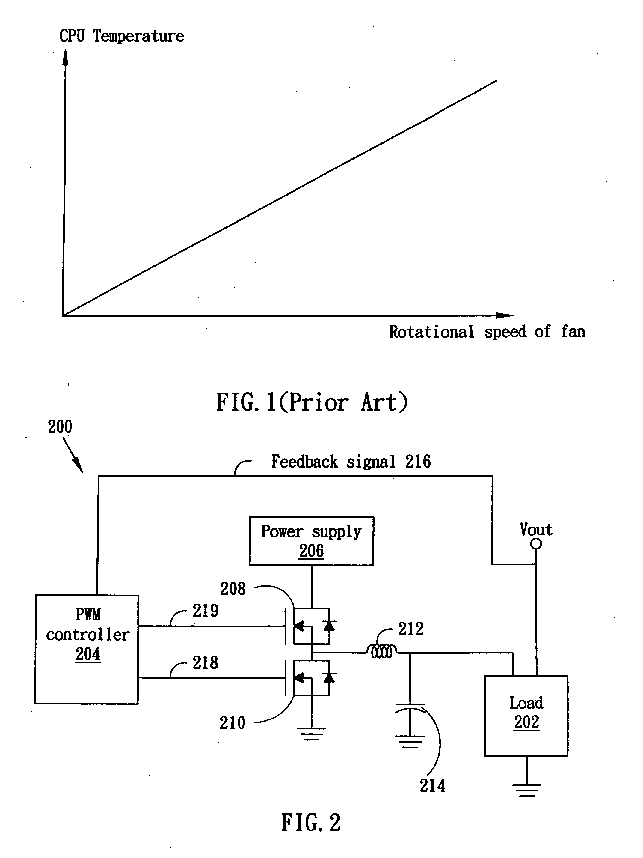
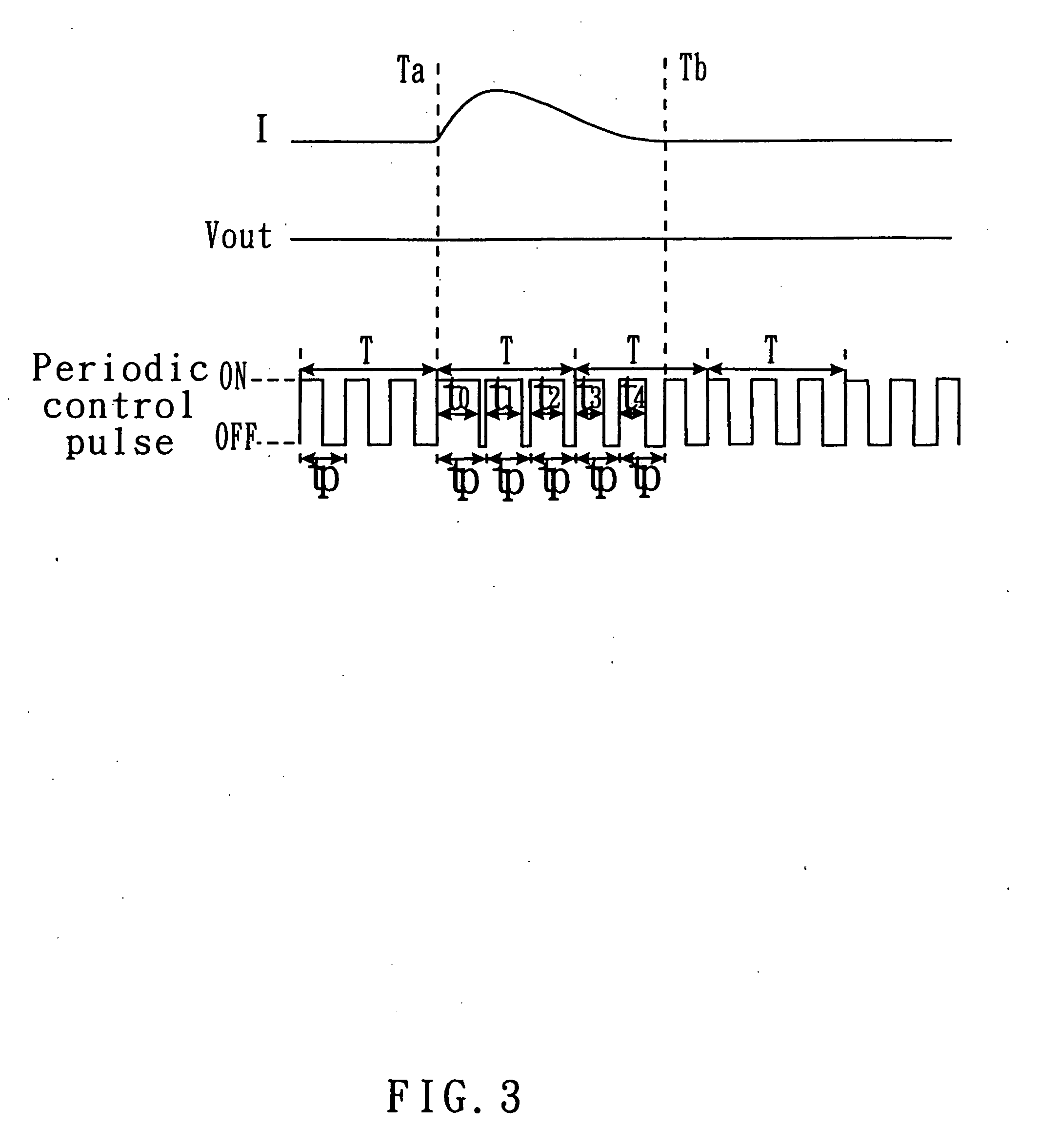
[0022]FIG. 2. shows a pulse-width-modulation (PWM) switching regulating circuit 200 according to the present invention. The regulating circuit 200 includes a load 202 (such as an electronic device, a controller chip, a server, or a CPU), a PWM controller 204, a power supply 206, a high-side metal oxide semiconductor (MOS) transistor 208, a low-side MOS transistor 210, and a filter made of an inductor 212 and a capacitor 214. Further, the output voltage Vout of the load 202 is fed back as a feedback signal 216 to the PWM controller 204. The PWM controller 204 is utilized to control the output voltage Vout to be within a regulated and working range. FIG. 3 shows the operating waveform of the PWM controller 204 of FIG. 2. Assuming that the load current I starts to increase at time Ta, the corresponding voltage across the load 202 will drop accordingly. In order to keep the output voltage Vout as stable as possible as shown in the figure, the PWM controller 204 thus increases the duty c...


PUM


Abstract

The invention is directed to a system and method for regulating a load (such as a CPU). A pulse-width-modulation (PWM) regulator calculates the duty cycle of the control pulse from a PWM controller, and then compares the duty cycle to a predetermined threshold. Thereafter, the PWM regulator regulates working conditions, such as clock frequency, supplied voltage, or fan spin speed, based on the above comparison.

Description

BACKGROUND OF THE INVENTION [0001] 1. Field of the Invention [0002] The present invention generally relates to load regulation, and more particularly to load regulation by using pulse width modulation (PWM). [0003] 2. Description of the Prior Art [0004] The detection of current plays an important role in electronic circuits, especially in power supply circuits. The power supply circuit provides the electronic circuit with needed current in a manner similar to that the human heart continuously provides the body with blood. As high blood pressure is harmful to health and thus precisely measuring the blood pressure is necessary, likewise precisely and instantaneously detecting the current is vital to the controllability of the electronic circuits. The current is conventionally detected by measuring the voltage drop across a resistor of known low resistance according to Ohm's law. However, this scheme has some disadvantages. Firstly, the accuracy of the current detection would be probab...

Claims


Application Information

Patent Timeline
Patent Type & Authority Applications(United States)
IPC IPC(8): H02P7/06
CPCF04D27/004Y02B30/70
Inventor CHIU, CHIH-KAICHEN, CHIEN-HUI
Owner AOPEN
Why Eureka
Try Eureka