

Method and apparatus to achieve a process, temperature and divider modulus independent PLL loop bandwidth and damping factor using open-loop calibration techniques
- Summary
- Abstract
- Description
- Claims
- Application Information
AI Technical Summary
Benefits of technology
Problems solved by technology
Method used
Image

Examples
first embodiment
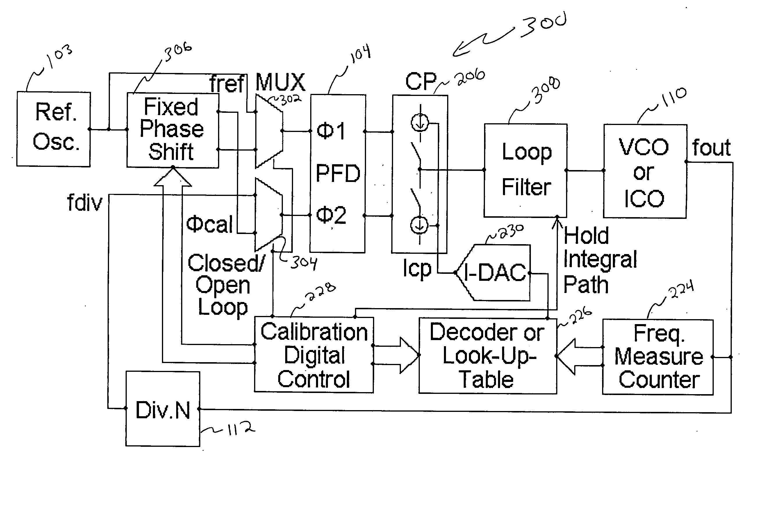
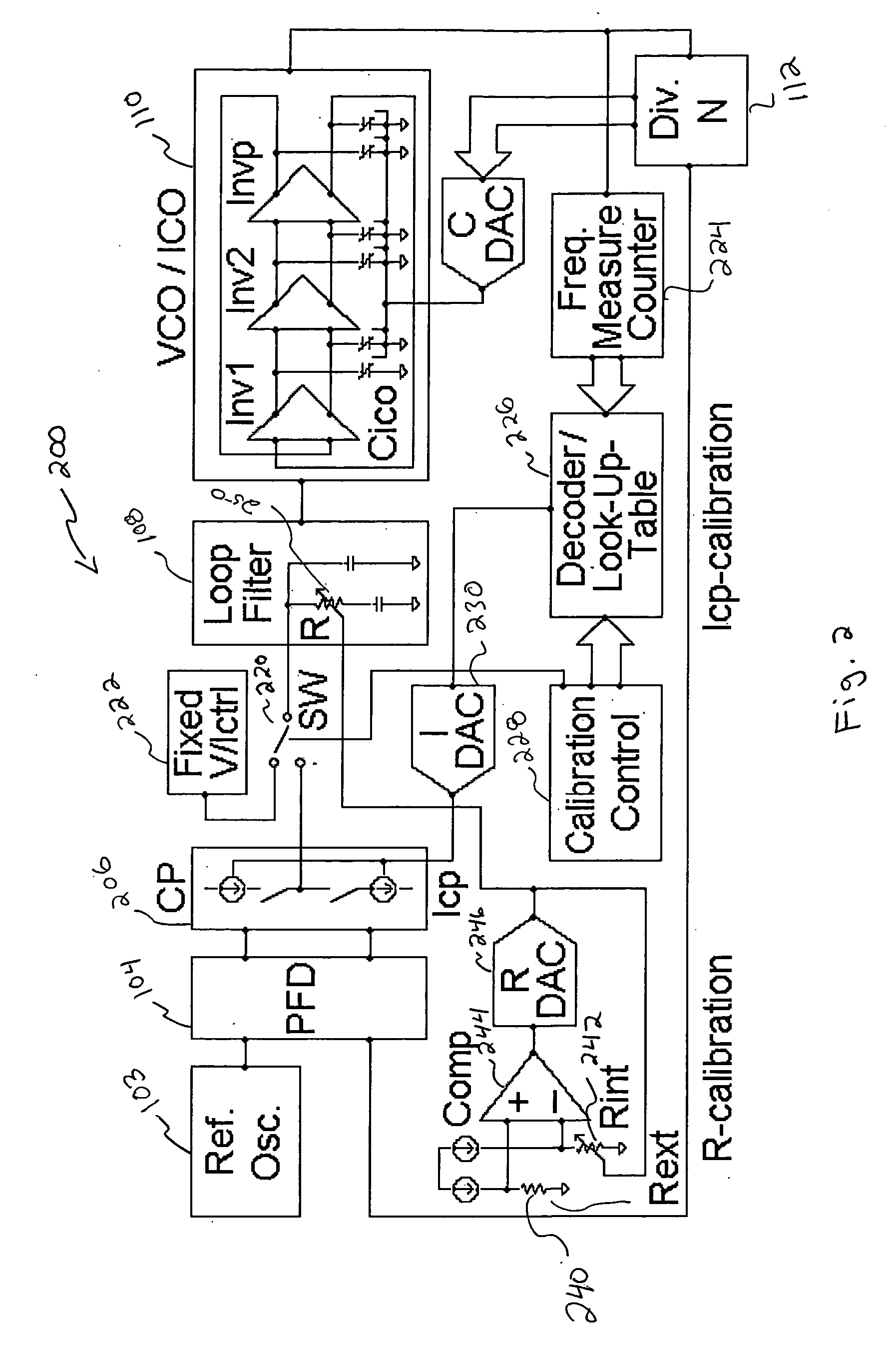
[0046]FIG. 2 presents the open-loop PLL calibration technique that uses a reduced complexity calibration circuit and involves only a single step measurement and a single element tuning.
[0047] The calibration techniques disclosed herein may comprise the following steps: [0048] opening the PLL feedback loop (for example, the easiest way to open the loop may be either disabling the phase frequency detector or powering down the charge-pump) [0049] applying a known stimulus to the opened loop signal path [0050] measuring the output signal (the output frequency of the oscillator or any divided down version of it) [0051] taking correction actions based on the measured value [0052] closing the PLL loop and starting the normal operation of the frequency synthesizer
In this manner, a technique is provided that applies a known stimulus to the PLL and allows for corrective adjustments based upon measurements obtained using the known stimulus. As will be described in more detail below, the know...
second embodiment
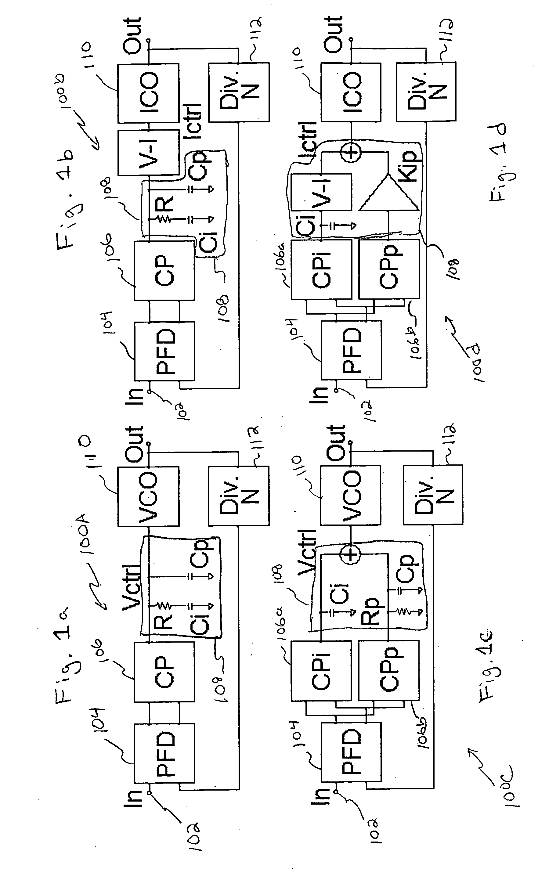
[0091]FIG. 4.b presents the integral path hold circuit suitable for the feed-forward loop filter architectures 308b. In this case two separate signal paths exist: the integral one built with the integral charge-pump 206a (CPi) and the integration capacitance (Ci) and the proportional path realized with the proportional charge-pump 206b (CPp), the proportional resistor (Rp) and the ripple pole capacitance (Cp). The two control signals (the integral and the proportional components) are summed together and control the oscillator. The summation process can be done either in the loop filter or in the oscillator. In the case of a current controlled oscillator an additional voltage-to-current converter stage needs to be introduced as shown. To hold the integral path the integral charge-pump is powered down or disabled and the integral capacitor (Ci) is shunted with SWhold switch 402 to the Vhold constant voltage 404.
[0092] The main advantages of this second embodiment of the open-loop PLL ...
PUM
 Abstract
Description
Claims
Application Information