
Evanescent-field optical amplifiers and lasers

a laser and optical amplifier technology, applied in the direction of lasers, electromagnetic transmission, transmission, etc., can solve the problems of easy result of distortion, significant fresnel reflection loss, inter-signal modulation problems, etc., and achieve the effect of high pumping efficiency

Inactive Publication Date: 2006-06-29
NAT CHIAO TUNG UNIV
View PDF5 Cites 7 Cited by
  • Summary
  • Abstract
  • Description
  • Claims
  • Application Information

AI Technical Summary

Benefits of technology

[0020] The main purpose of the present invention is to provide an optical amplifier and a laser, which have a high pumping efficiency by utilizing a side-polished fiber cooperating with a highly rare-earth-ion doped optical gain medium and a grating inscribed in a guiding core near the evanescent-field to couple almost entire pumping power toward the optical gain medium.
[0043] Preferably, the volume of the filler is adjusted in response to one selected from a group consisting of a thermo-optic effect, a piezo-electric effect and an acousto-optic effect.
[0044] Another purpose of the present invention is to provide an optical amplifier and a laser, which have a high pumping efficiency by utilizing a side-polished fiber with an optical gain medium having a dopant of rare-earth ions and a grating inscribed in a guiding core near the evanescent-field to couple almost entire pumping power toward the optical gain medium.

Problems solved by technology

Problems of the inter-signal modulation and the distortion are easily resulted from the channel crosstalk, the four-wave mixing and the sensitivity to the polarization while the semiconductor amplifier is used for the dense wavelength division multiplexing (DWDM) system.
Furthermore, a large refractive index difference between the semiconductor material and the transmission fiber leads to significant Fresnel reflection losses.
However, an amplifying medium of a long-distance fiber and a high-power pumping laser are required due to the poor nonlinear coefficients of the silica fibers.
As a result, the cost is expensive and the efficiency is less than those of the doped fiber amplifier.
The intensity decaying will make the signal have a poor signal-to-noise ratio (SNR) and seriously influence the transmission quality.
Furthermore, the energy of the light signal can be directly amplified by the EDFA and a complicated optic-electro transformation is needless to involve.
However, efforts to overcome the difficulties relative to the structure of EDFA are still necessary to be done.
Since the modified chemical vapor deposition (MCVD) processing of the EDFA is employed, the erbium ion concentration is not easily to be controlled to prevent the up-conversion or the pair-induced quenching resulted from the uneven distribution of erbium ions, which cause a lower quantum efficiency.
Therefore, the length of the erbium doped fiber must be long enough (>1 m) to achieve the amplification and thus the volume of the optical amplifier cannot be effectively reduced.
Although the pumping light and the signal light can most compactly and effectively overlap by completely doping the optical gain medium into the guiding core, the amplified spontaneous emission is limited in the guiding core and continuously amplified.
This effect leads to a competition for the optical gain between the amplified spontaneous emission and the signal light and a poor SNR of the signal.
Because there was no optical resonating system involved in this method and the refractive index of the dye was not easy to closely control to the effective refractive index of the waveguide, they had just shown that the optical amplification can be achieved based on the pumping through evanescent-field coupling.
On the other hand, in order to prevent the signal energy loss resulted from an over-penetration of the signal light, the leaky depth of the signal evanescent-field has to be limited and thus the leaky depth of the pumping light beam is not enough to excite the optical gain medium.
Hence a filter is needed to filter the unused pumping power away in front of the receiver and this would result in an additional energy consuming.
Therefore, it is difficult to simultaneously obtain a better exciting efficiency and an appropriate penetration of the signal evanescent-field.
Besides, the optical gain amplification was not effectively enhanced due to a poor technique for the fiber polishing and therefore the effective interaction length of the side-polished fiber was not long enough.
However, a high-density overlap among the pumping energy, the signal energy and the optical gain medium cannot be obtained by this kind of excitation method.
Thus an optical gain with high quantum efficiency is difficult to achieve.
Moreover, the method of the signal incidence, which is perpendicular to the optical waveguide is not practical in the optical communication.
However, the pumping efficiency is still not significantly improved because the optimal evanescent-field leaky depths of the signal and the pumping light cannot be obtained simultaneously, either.

Method used


Image

  • Evanescent-field optical amplifiers and lasers
  • Evanescent-field optical amplifiers and lasers
  • Evanescent-field optical amplifiers and lasers

Examples


Embodiment Construction

[0070] The present invention will now be described more specifically with reference to the following embodiments. It is to be noted that the following descriptions of preferred embodiments of this invention are presented herein for purpose of illustration and description only; it is not intended to be exhaustive or to be limited to the precise form disclosed.

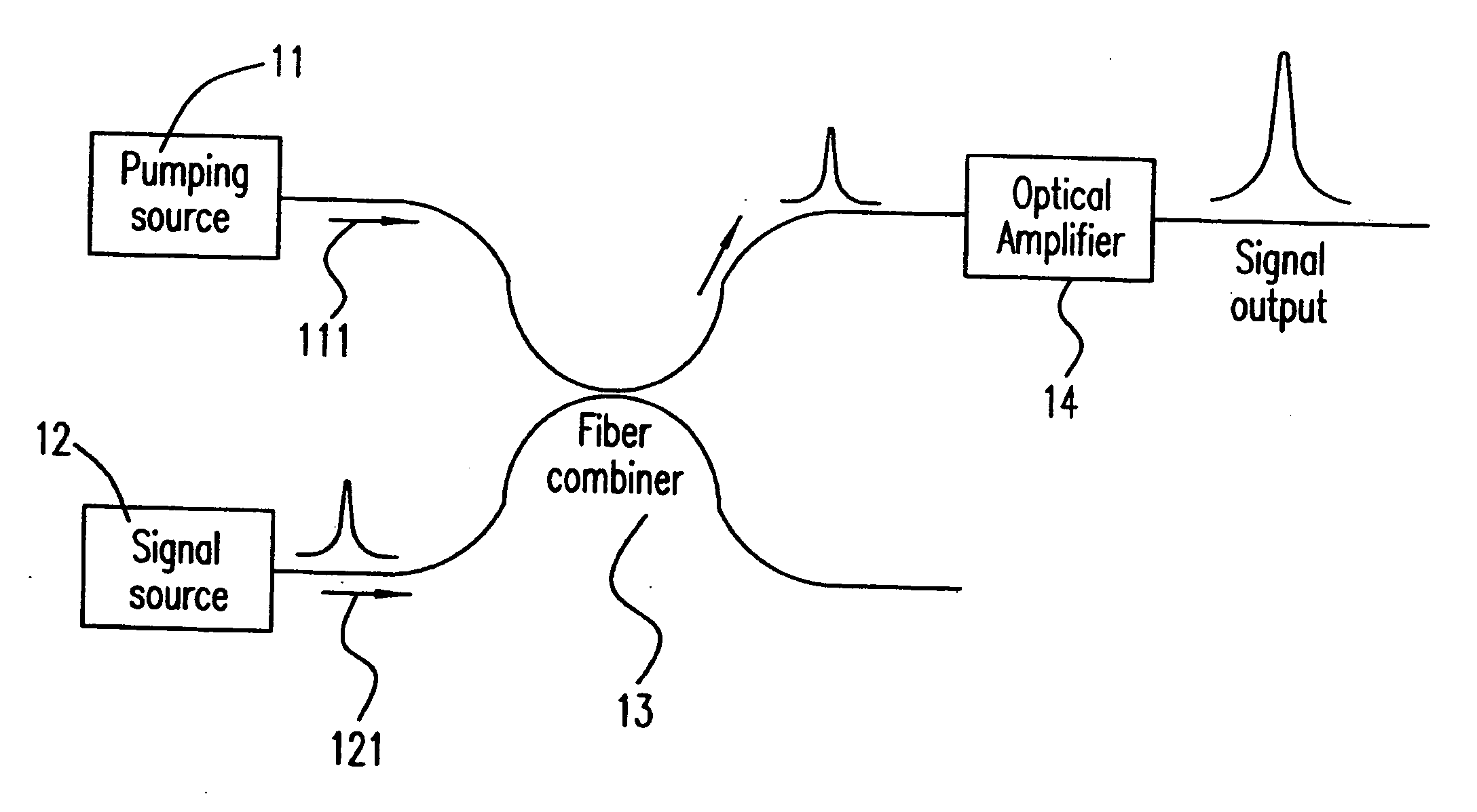
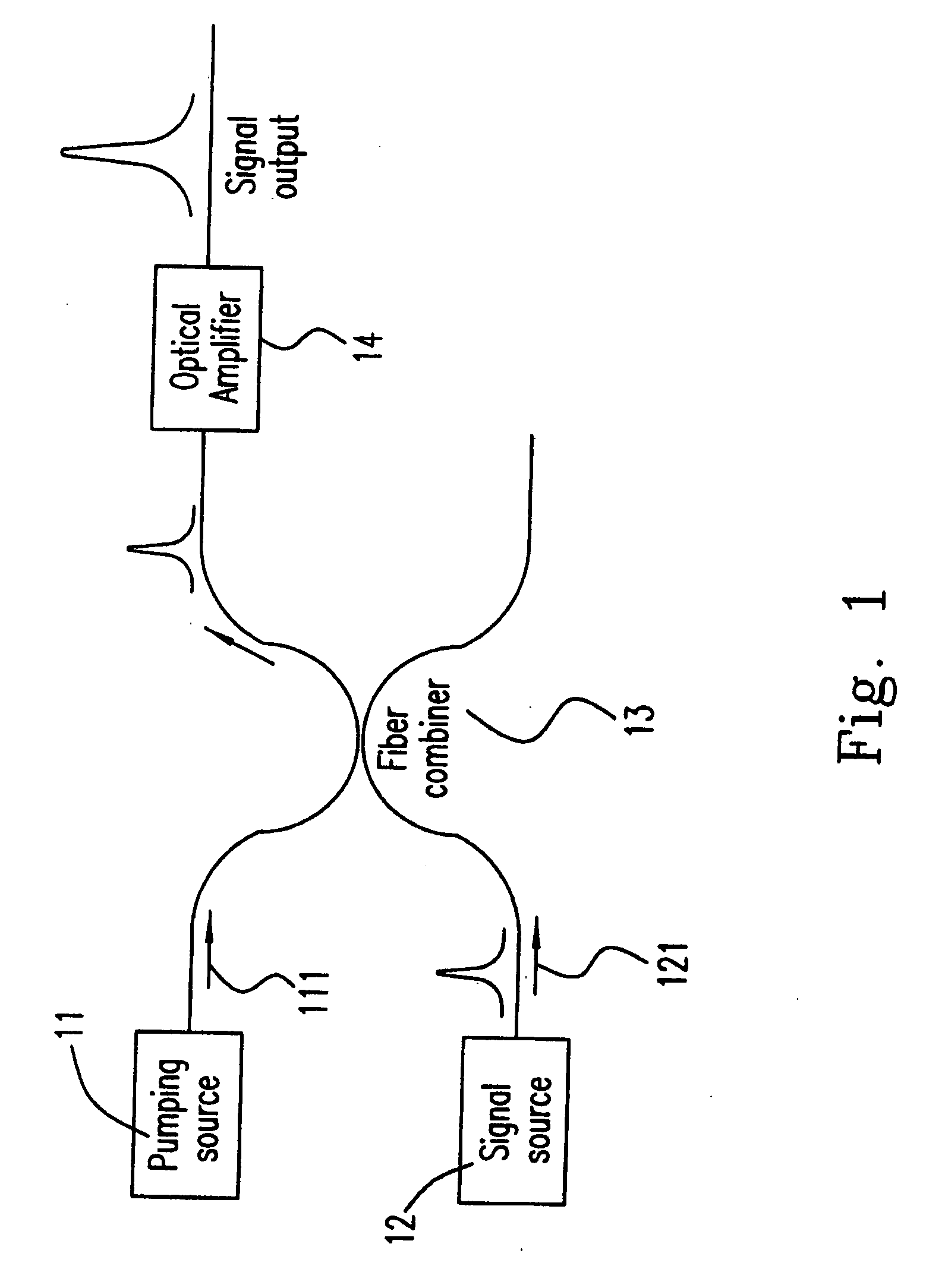
[0071] Please refer to FIG. 1, which illustrates the principle of the optical amplifier according to the present invention. The pumping light beam 111 from the pumping source 11 and the signal light beam 121 from the signal source are collected by the fiber combiner 13 and then propagate in a fiber (not shown). By an optical gain of the optical amplifier 14, which is related to the present application, a signal output having a higher intensity and a specific wavelength can be generated and continuously propagate in the fiber.

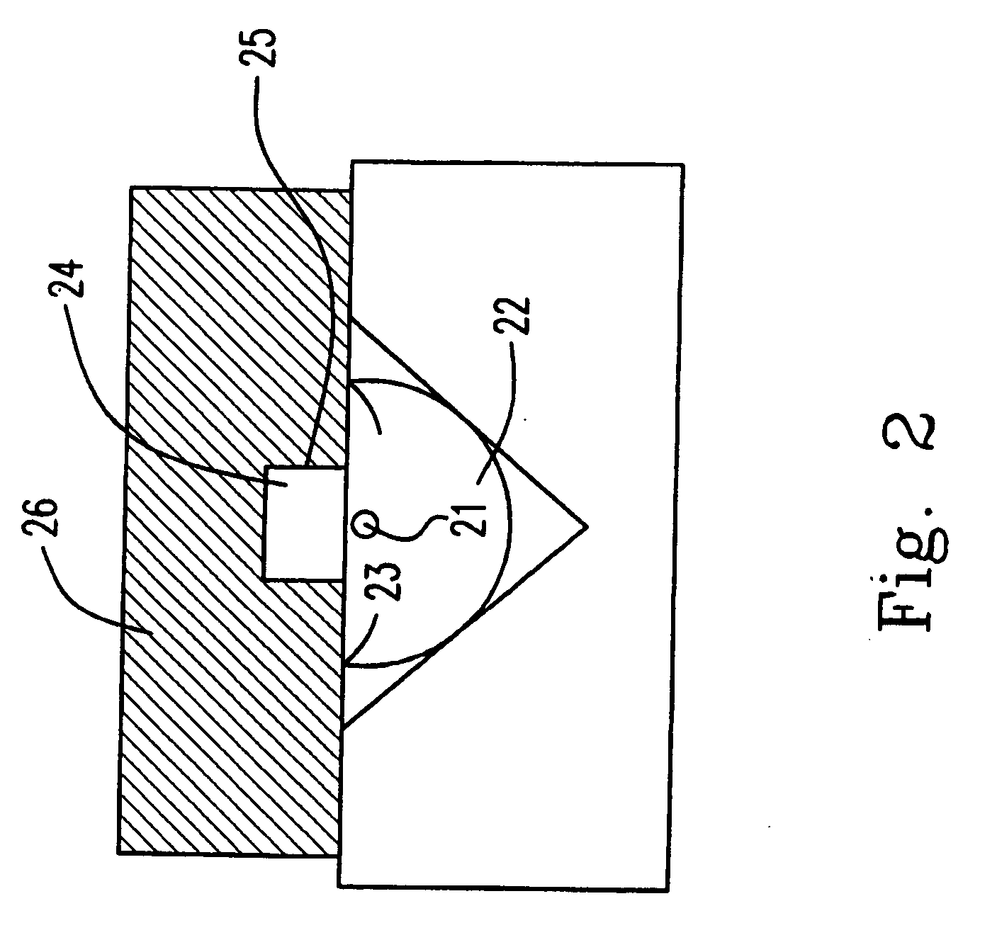
[0072] Please refer to FIG. 2, which illustrates the structure of the optical amplifier according to a ...


PUM


Abstract

An optical amplifier and a laser generator based on the fiber side-polished technology, having a high pumping efficiency, a low noise figure and a small footprint are provided in this application. The optical amplifier and the laser, which have a very long effective interaction length in conjunction with highly doped Erbium glass attached to its surface and an addition of a slanted fiber grating inscribed in the guiding core at the polished region can spatially separate the signal and pump power to simultaneously improve the pumping efficiency and optimize the penetrated depth of the signal evanescent-field. The spontaneous emission is kept from being amplified and therefore a high quality amplified signal is produced.

Description

CROSS REFERENCE TO RELATED APPLICATION [0001] This application is a divisional of U.S. patent application Ser. No. 10 / 833,437, filed on Apr. 28, 2004, which is incorporated by reference as if fully set forth.FIELD OF THE INVENTION [0002] The present invention relates to an optical amplifier and a laser, in particular to the optical amplifier and the laser, which have an optical gain medium overlaying the evanescent-field of a side-polished fiber and a grating inscribed in a guiding core in side-polished region. BACKGROUND OF THE INVENTION [0003] The optical amplifier, which is one of the most important devices for the optical communication system, can regenerate a light signal, which is attenuated while transmitting and dividing. Therefore, the development of an optical amplifier, which has a smaller volume, less noise and lower price will have a great effect on the metropolitan and the access network in the future. [0004] In chief, three kinds of optical amplifiers are widespread i...

Claims


Application Information

Patent Timeline
Patent Type & Authority Applications(United States)
IPC IPC(8): H01S3/00H01S3/067H01S3/094
CPCH01S3/06708H01S3/094003H01S3/06729
Inventor CHEN, NAN-KUANGCHI, SIENTSENG, SHIAO-MINLAI, YINCHIEH
Owner NAT CHIAO TUNG UNIV
Learn More