Indirectly heated cathode and cathode ray tube having same

a cathode and ray tube technology, applied in the direction of discharge tube/lamp details, discharge tube main electrodes, discharge tube solid thermionic cathodes, etc., can solve the problems of inability to properly display the image, inability to achieve proper image display, and large color balance disturbance of display image, etc., to achieve good image display, reduce the effect of heat deformation of the cathode sleeve, and reduce the effect of sleeve temperatur

Inactive Publication Date: 2006-07-06
PANASONIC CORP
View PDF6 Cites 2 Cited by
  • Summary
  • Abstract
  • Description
  • Claims
  • Application Information

AI Technical Summary

Benefits of technology

[0014] According to this construction, the heat deformation of the cathode sleeve can be suppressed more effectively.
[0015] A cathode ray tube having the indirectly heated cathode of the above construction has little variations in cutoff voltage even when operated for a long time, with it being possible to maintain a favorable image display.

Problems solved by technology

If the cutoff voltage varies, a proper image display cannot be achieved.
Especially in the case of color cathode ray tubes that use three cathodes for R, G, and B, a color balance of a display image is greatly disturbed if the cutoff voltage in each cathode changes, which makes it impossible to properly display the image.
This type of indirectly heated cathode, however, requires a complex manufacturing process since the crystal structure needs to be formed by repeating annealing and rolling.
Furthermore, a sufficient resistance to heat deformation cannot be attained.

Method used


Image

  • Indirectly heated cathode and cathode ray tube having same
  • Indirectly heated cathode and cathode ray tube having same
  • Indirectly heated cathode and cathode ray tube having same

Examples


example 1

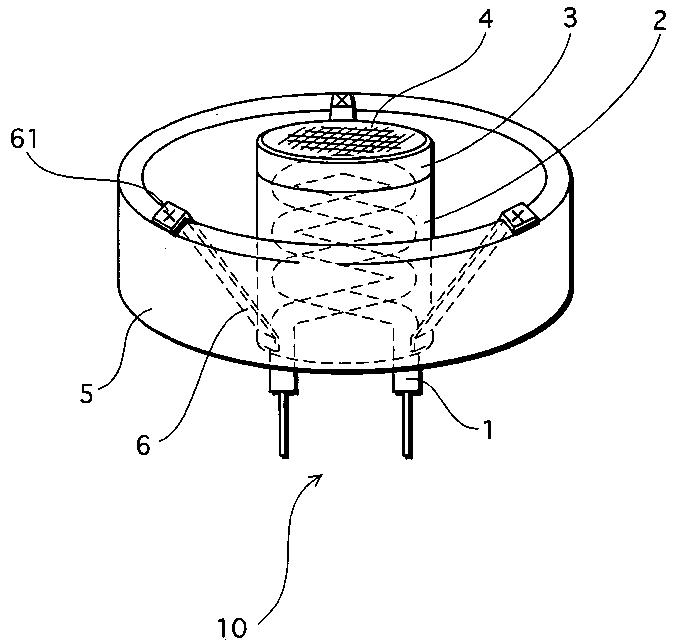
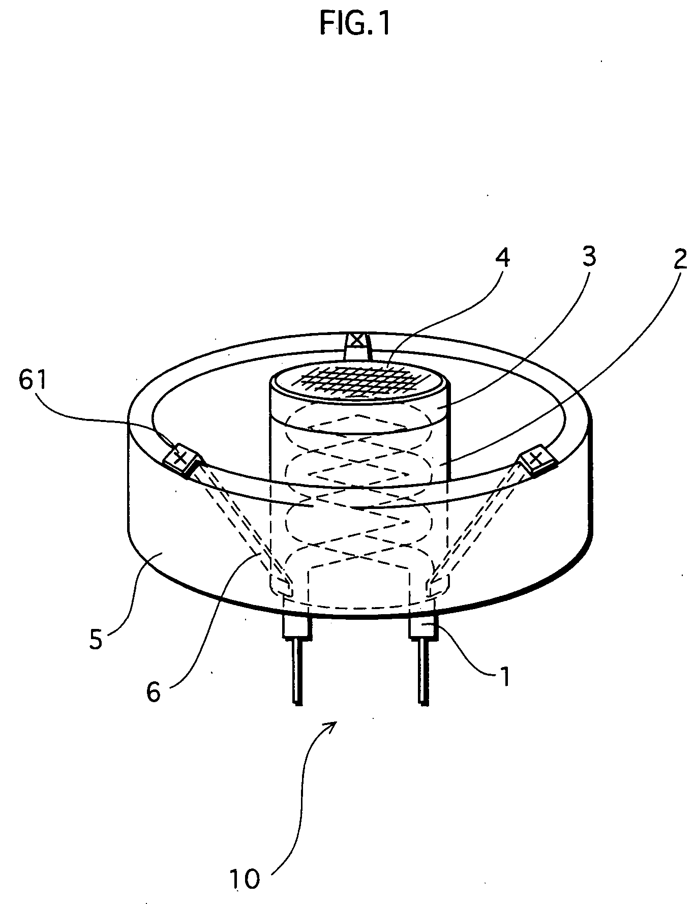
[0043] An accelerated life test was conducted on a 32-inch cathode ray tube having an electron gun in which three indirectly heated cathodes 10 of the embodiment are arranged in-line.

[0044] Here, the cathode sleeve 2 is a cylinder with a diameter of 1.57 mm, a height of 2.5 mm, and a thickness of 0.05 mm. A material of the cathode sleeve 2 is an Ni—Cr alloy containing Si (0.18 wt %), Al (0.008 wt %), Ce (0.009 wt %), and La (0.02 wt %). Also, a black coating of chromic oxide is formed on the surface of the cathode sleeve 2.

[0045] The same test was conducted on a cathode ray tube having a conventional indirectly heated cathode that does not contain Ce and La, as a comparative example.

[0046]FIG. 5 shows variations (ΔV) in cutoff voltage relative to elapsed times, when operating the cathode ray tube for a predetermined time period. The horizontal axis represents an operation time of the cathode ray tube, whereas the vertical axis represents a variation in cutoff voltage by %.

[0047]...

example 2

[0053] Experiments were conducted about a relationship between a content of each additive (impurity) in the cathode sleeve of the indirectly heated cathode according to the embodiment and an expansion ratio of the cathode sleeve after heat treatment, in order to determine an optimal range of the content of each additive. FIGS. 6A, 6B, and 6C show results of these experiments.

[0054]FIGS. 6A, 6B, and 6C respectively show expansion ratios of the cathode sleeve relative to contents of Si, Al, and Ce in the Ni—Cr alloy. The horizontal axis represents a content of a corresponding metal (wt %), whereas the vertical axis represents an expansion ratio of the cathode sleeve in the direction A (see FIG. 7) by %.

[0055] In this example too, an accelerated life test was conducted on a 32-inch cathode ray tube having an electron gun with three indirectly heated cathodes arranged in-line. Each of these indirectly heated cathodes includes a cathode sleeve that is of the same size as the above exam...


PUM

PropertyMeasurementUnit
temperatureaaaaaaaaaa
lengthaaaaaaaaaa
cutoff voltageaaaaaaaaaa

Abstract

An indirectly heated cathode includes a cathode sleeve (2) housing a heater (1), a caplike base (3) attached onto the cathode sleeve (2), and an electron emitter layer (4) formed on a surface of the base (3). The cathode sleeve (2) is made of a metal material that contains nickel and chromium as main components and further contains at least silicon, aluminum, cerium, and lanthanum. According to this construction, the cathode sleeve (2) is kept from heat deformation. Hence a reliable indirectly heated cathode which suppresses variations in cutoff voltage can be realized.

Description

TECHNICAL FIELD [0001] The present invention relates to an indirectly heated cathode having a cathode sleeve, and to a cathode ray tube which includes the indirectly heated cathode. BACKGROUND ART [0002] An indirectly heated cathode, such as an indirectly heated cathode 100 shown in FIG. 7, is conventionally used as a cathode of an electron gun which is housed in a neck of a cathode ray tube. [0003] As shown in the drawing, the indirectly heated cathode 100 includes a cylindrical cathode sleeve 102 enclosing a spiral heater 101, a caplike base 103 provided on the cathode sleeve 102, and an electron emitter layer 104 formed by coating an upper surface of the base 103 with an electron emitting material such as an alkaline earth metal using a spray or the like. [0004] The cathode sleeve 102 is placed in a cylindrical cathode holder 105, and held by the cathode holder 105 via cathode supporters 106. [0005] The cathode sleeve 102 has a function of transmitting heat generated from the hea...

Claims


Application Information

Patent Timeline
Patent Type & Authority Applications(United States)
IPC IPC(8): H01J1/20H01J1/14H01J29/04
CPCH01J1/14H01J1/20H01J29/04
Inventor YAMAGISHI, MIKA
Owner PANASONIC CORP
Why Eureka
Try Eureka