Bioimplant with nonuniformly configured protrusions on the load bearing surfaces thereof

Active Publication Date: 2006-07-06
WARSAW ORTHOPEDIC INC
View PDF28 Cites 71 Cited by
  • Summary
  • Abstract
  • Description
  • Claims
  • Application Information

AI Technical Summary

Benefits of technology

[0023] In accordance with one aspect of the invention, the protrusions, taken as a complete system on both load bearing surfaces of the implant, are arranged to resist lateral displacement in all directions. This may be accomplished by having different, complementary patterns of protrusions on the top and bottom load bearing surfaces, or by having similar, or identical multidirectional protrusions on each surface. An example of complementary protrusions is ridges that run parallel to reach other on a given surface, but at an angle (preferably perpendicular) when comparing one face to another. An example of multidirectional protrusions is a circular or semicircular pattern of ridges. An example of an existing multidirectional pattern is a series of pyramidal shapes, which are made by patterns of intersecting ridge lines. By nature, these patterns require at least two machining steps, to form each of the intersection grids. The preferred patterns of the present invention can be made by one machining step (using a shape, multi-point cutting tool). It is easy to see how parallel patterns or circular patterns can be made in one step. An obvious advantage of one step machining is a savings in time and part set-up.
[0024] In accordance with another aspect of the invention, the size of the protrusions on the load-bearing surfaces of the bioimplant may be varied within multiple clusters, groups or sections of the protrusions to compensate for uneven distribution of compressive loads applied in multiple directions. Even in the context of a substantially unidirectional force, some of the protrusions may be under higher stress than others due to a variety of factors associated with each given surgical site and including, among others, geometrical, topographical and force-distribution factors. Also, a bioimplant may have relatively w

Problems solved by technology

Spinal discs may be displaced or damaged due to trauma, disease or aging.
The extruded nucleus pulposus may press on the spinal nerve, which may result in nerve damage, pain, numbness, muscle weakness and paralysis.
Intervertebral discs may also deteriorate due to the normal aging process or disease.
As a disc dehydrates and hardens, the disc space height will be reduced leading to instability of the spine, decreased mobility and pain.
Collapse of the disc space can cause instability of the spine, abnormal joint mechanics, premature development of arthritis or nerve damage, in addition to severe pain.
Success of the discectomy and fusion procedure requires the development of a contiguous growth of bone to create a solid mass because the implant may not withstand the cyclic spinal loads for the life of the patient.
However, the composition of the implant alone is not necessarily sufficient to provide a high rate of fusion.
Once in situ, the osteogenic implant is exposed to multidirectional compressive loads tending to cause the implant to translate, which, in turn, may cause neural and vascular injury, as well as collapse of the disc space.
One of the consequences of relativ

Method used


Image

  • Bioimplant with nonuniformly configured protrusions on the load bearing surfaces thereof
  • Bioimplant with nonuniformly configured protrusions on the load bearing surfaces thereof
  • Bioimplant with nonuniformly configured protrusions on the load bearing surfaces thereof

Examples


Embodiment Construction

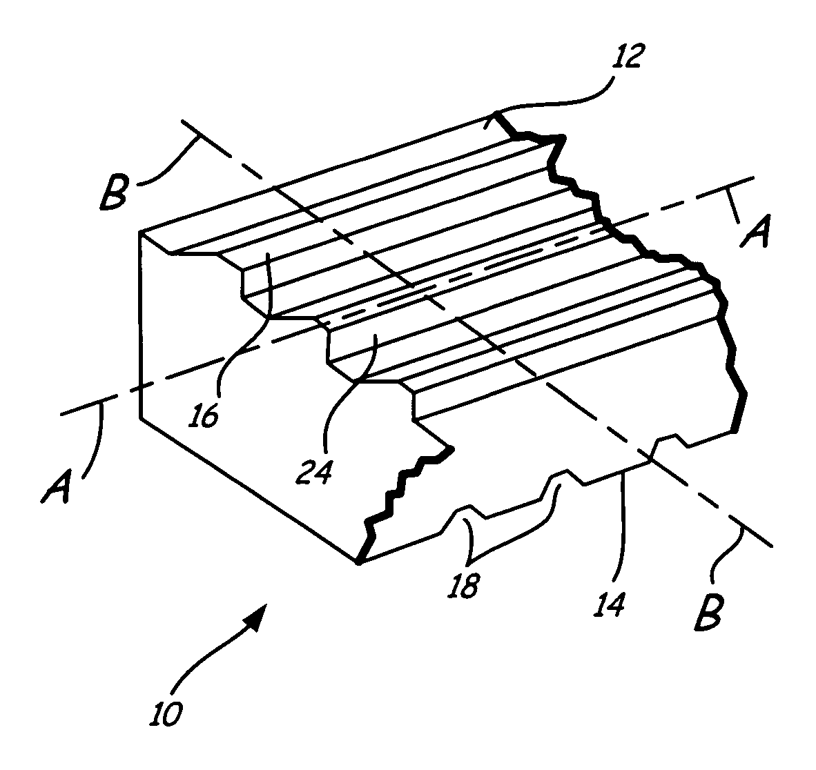
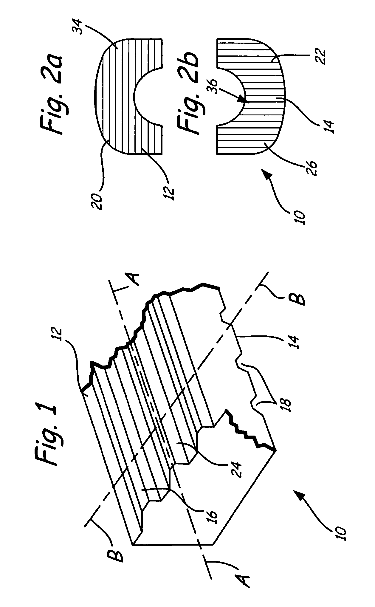
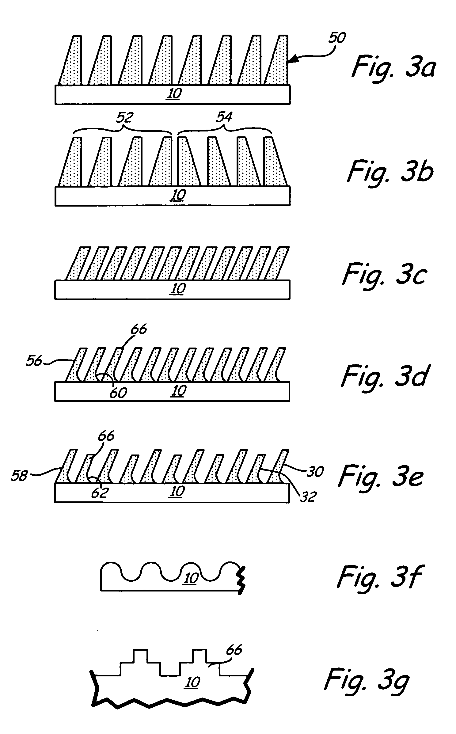
[0029] Referring to FIGS. 1 and 2, a surgical bioimplant 10 useful as an intervertebral implant is provided with load bearing surfaces typically juxtaposed with end plates of adjacent vertebrae (not shown) and configured to improve stabilization of the implant at the surgical site by gradually fusing the bearing surfaces with the end plates. The term “bioimplant” as used herein, refers to an implant comprising cortical and / or cancellous bone, from autograft, allograft or xenograft origin, which is processed for implantation into a living patient. The term “stability” as used herein, refers to the ability of the textured bioimplant to remain at an implantation site without significantly shifting, rotating, or being extruded.

[0030] Note, however, that implant 10 may be manufactured from other suitable implant materials, which are capable of withstanding the compression and torsional loads. Among others, such material may include composites of Hydroxyapatite, calcium carbonates, calci...


PUM


Abstract

A bioimplant is configured with at least two load-bearing surfaces each having a plurality of protrusions oriented at an angle with respect to one another to resist translation in all directions when opposing load bearing surfaces are under normally applied compressive loads.

Description

CROSS REFERENCE TO RELATED APPLICATION [0001] This application claims the benefit of U.S. Provisional Application Ser. No. 60 / 475,805, filed Jun. 3, 2003, the entire contents of which are incorporated by reference herein.BACKGROUND OF THE INVENTION [0002] 1. Field of the Invention [0003] This invention is generally directed toward a surgical bioimplant. Particularly, the invention relates to the geometry of the bioimplant's load bearing surfaces configured to improve resistance of the bioimplant to omnidirectional translations at the surgical site. [0004] 2. Description of the Prior Art [0005] Spinal fusion is directed to provide stabilization of the spinal column for painful spinal motion and disorders such as structural deformity, traumatic instability, degenerative instability, and post-resection instability. Fusion, or arthrodesis, is achieved by the formation of an osseous bridge between adjacent motion segments. This can be accomplished within the disc space, anteriorly betwee...

Claims


Application Information

Patent Timeline
IPC IPC(8): A61F2/44A61F2/28A61BA61F2/00A61F2/30A61F2/46
CPCA61F2/30771A61F2/4455A61F2002/2835A61F2002/30059A61F2002/30113A61F2002/30125A61F2002/30131A61F2002/30136A61F2002/30151A61F2002/30153A61F2002/30154A61F2002/30156A61F2002/30158A61F2002/30159A61F2002/30205A61F2002/30224A61F2002/30263A61F2002/30273A61F2002/30828A61F2002/30879A61F2002/30892A61F2002/4649A61F2230/0004A61F2230/0006A61F2230/0008A61F2230/0013A61F2230/0017A61F2230/0019A61F2230/0021A61F2230/0023A61F2230/0026A61F2230/0028A61F2230/0067A61F2230/0069A61F2230/0084A61F2230/0086A61F2310/00293A61F2/28A61F2/44A61B17/70A61B17/68
Inventor SHIMP, LAWRENCE A.WINTERBOTTOM, JOHN
Owner WARSAW ORTHOPEDIC INC
Why Eureka
Try Eureka