Prosthetic spinal discs

a spinal disc and prosthetic technology, applied in the field of prosthetic devices, can solve the problems of disc disease limiting spinal motion or cushioning, pain, loss of muscle control or even paralysis, chronic and severe back pain, etc., to reduce the overall thickness of compressed springs, reduce the overall stress, and reduce the effect of localized stress

Active Publication Date: 2006-07-06
INFINESSE CORP
View PDF34 Cites 67 Cited by
  • Summary
  • Abstract
  • Description
  • Claims
  • Application Information

AI Technical Summary

Benefits of technology

[0046] If the prosthesis does not have plates, the spring coils should be designed such that their contact with the vertebrae does not create unacceptable localized stress on the vertebrae. Increasing the contact area of the spring to the vertebrae by shaping the coil wire and shaping the coil itself will minimize localized stress. Flattening the outer, top surface of a round diameter wire coil increases the contact area while flattening the bottom surface reduces the overall compressed spring thickness. Likewise, having a low spring pitch at the ends of the spring increases the length of the spring that contacts the vertebrae.

Problems solved by technology

Unfortunately, disc disease limits spinal motion or cushioning or only permits the motion with pain.
The herniated nucleus can compress a spinal nerve, which results in pain, loss of muscle control or even paralysis.
This also causes chronic and severe back pain.
Whenever the nuclear tissue is herniated or the disc degenerates, the disc space narrows and the adjacent vertebra may lose much of their normal stability.
While this treatment usually alleviates the pain, the patient loses all disc motion in the fused segment.
The added stress may lead to premature degeneration of those adjacent discs.
Friction causes one problem in this device.
This causes the prosthetic disc to function improperly.
The jacket is flexible but inelastic.
Therefore, the jacket allows the hydrogel core to deform and reform as it is loaded and unloaded, but the jacket limits the core's horizontal and vertical expansion
Some are concerned that prostheses that use gel or polymer will lose the resiliency or the resiliency will change over the many cycles of loading and unloading.
This biological activity can cause the prosthesis to lose its grip with the surrounding bone tissue.
However, Patil also fails to provide natural motion for adjacent vertebrae.
Each of these devices is problematical.
If the coils touch and depending on how they touch, the touching can create a sound, which is unnatural and can be unpleasant.
Further, when adjacent coils rub against each other, microscopic pieces of metal can rub off the spring.
Using a plastic spring does not solve the problem because plastic molecules also can rub off.
Further, plastic may not be strong enough for the small springs necessary.
However, prior art spring prostheses fail to consider proper spring design.
Moreover, the spring must be limited in size.
Prior art metal spring prosthesis usually have alignment problems.
These problems can cause the springs to work unevenly.
Having many different versions of specially configured springs available for a surgery can be costly, however.
In addition, fabrication costs for specialized springs are greater.
Surgical procedures for disc replacement are very complex and subject to many complications.
Aligning and securing present prostheses can be very difficult and time consuming.

Method used


Image

  • Prosthetic spinal discs
  • Prosthetic spinal discs
  • Prosthetic spinal discs

Examples


Embodiment Construction

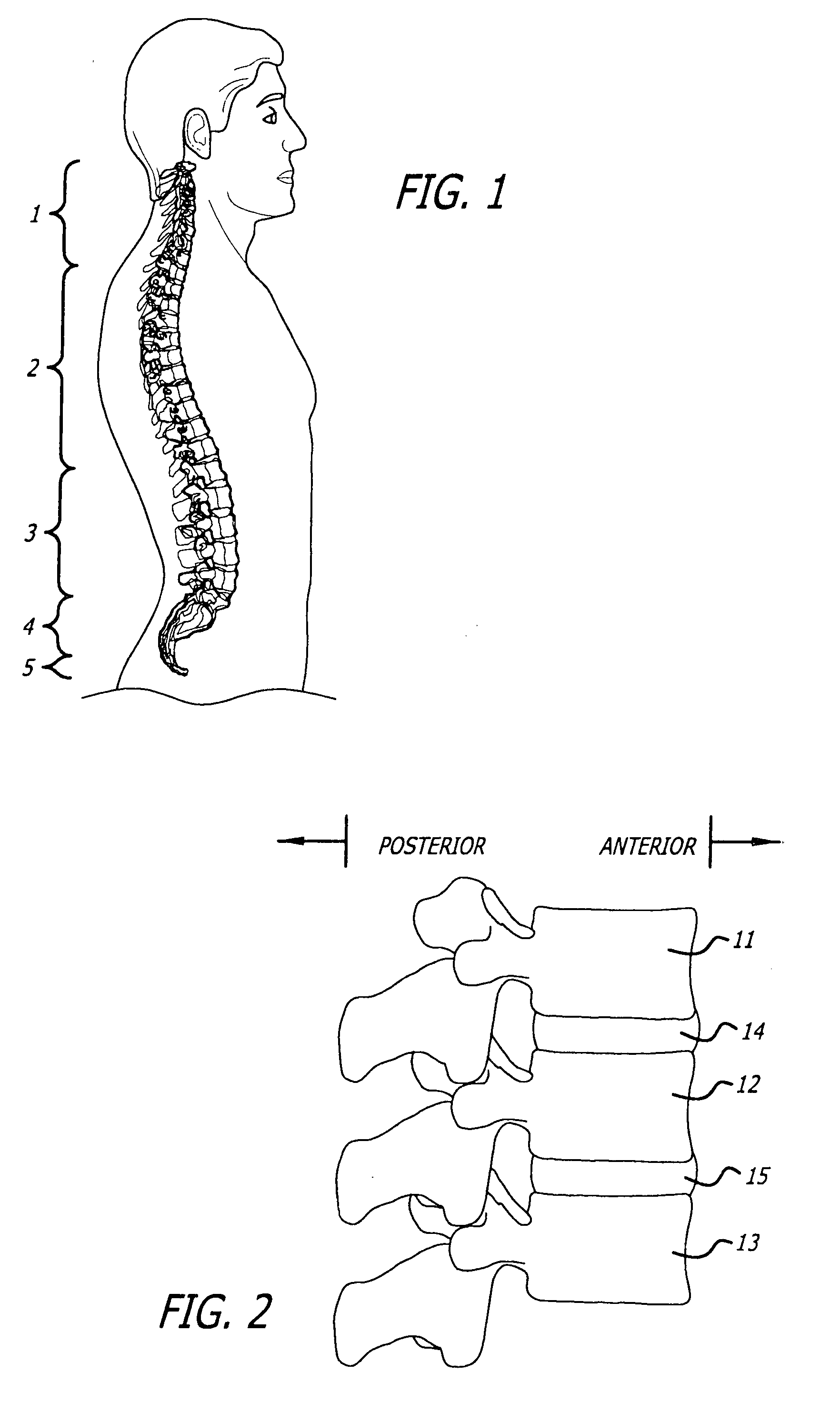
[0070]FIG. 1 is a representation of a human spine. The vertebrae include seven cervical vertebrae 1 in the neck, 12 thoracic vertebrae 2 below the neck, five lumbar vertebrae 3 of the lower back, one sacrum 4 below the lumbar region and one coccyx 5.

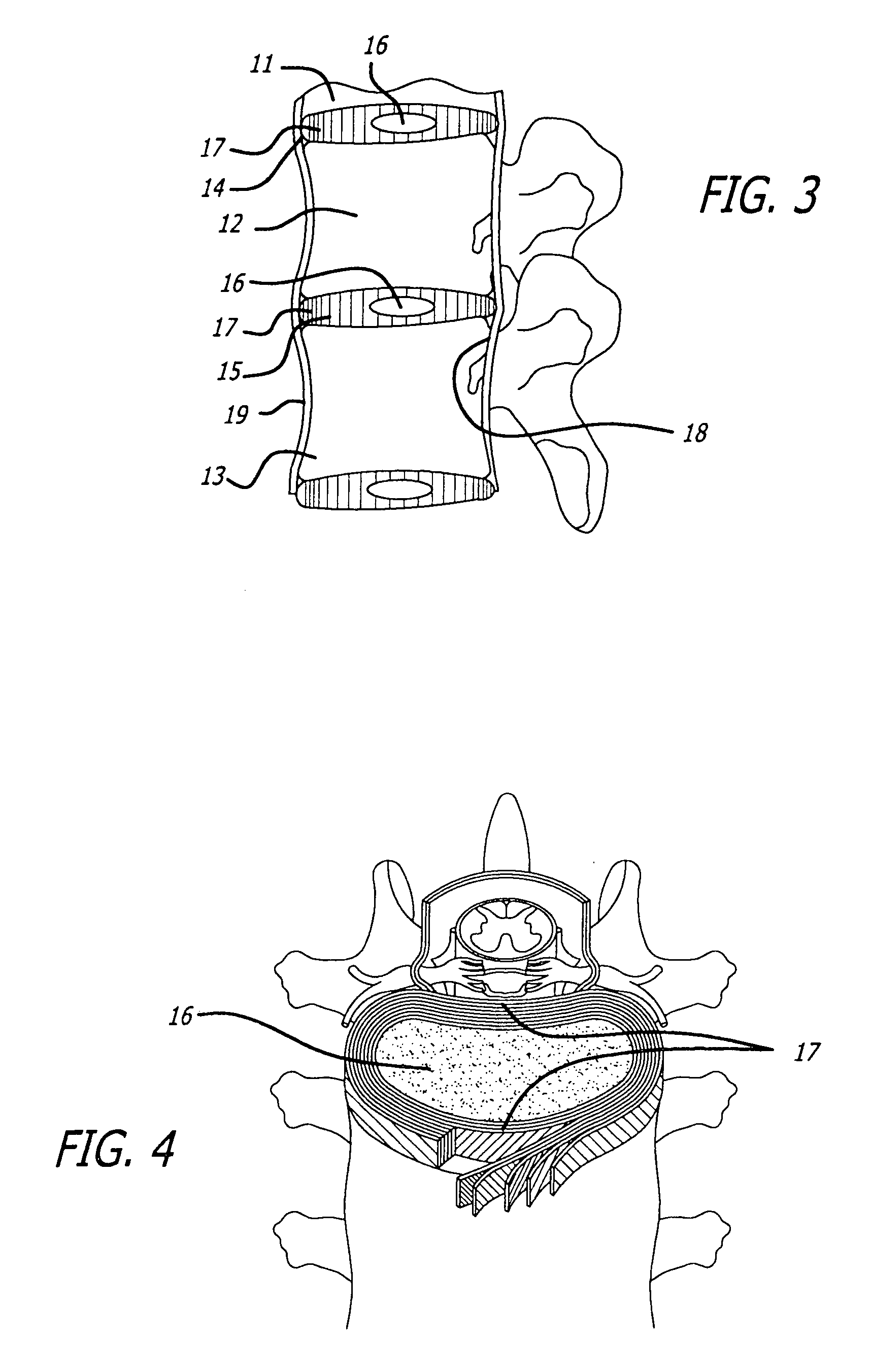
[0071] The adjacent vertebral bodies 11, 12 and 13 (FIGS. 2 and 3) are separated by intravertebral discs 14 and 15. Each disc has a nucleus pulposus 16 surrounded by an annulus fibrosus 17. See also FIG. 4. FIG. 3 also shows the posterior longitudinal ligament 18 and the anterior longitudinal ligament 19, which secure the vertebrae and disc together. Other ligaments, which are not discussed, also are present.

[0072] The representation of a disc in FIG. 4 shows the nucleus pulposus surrounded by the outer annulus fibrosus. The annulus fibrosus acts as a constraining ring primarily composed of collagen. It allows the intervertebral disc to rotate or bend without significantly affecting the hydrostatic pressure of the nucleus pulposus. The...


PUM


Abstract

A prosthetic spinal disc uses a stiff spring or springs for resiliency between two plates that attach to adjacent vertebrae. When the disc has multiple springs, they may be adjacent, concentric or nested. Multiple springs may be spaced around the periphery of the plates. A foil metal bellows may surround the plates to prevent material from entering or exiting the space between the plates. Alternatively, the ends of the spring(s) may be machined with spikes to engage the vertebrae directly without plates.

Description

BACKGROUND OF THE INVENTION [0001] 1. Field of the Invention [0002] The present invention relates to prosthetic devices used to replace diseased or damaged spinal discs. [0003] 2. General Background and State of the Art [0004] The adult spine has 26 vertebrae (depending how one counts) with fibrocartilage, intervertebral discs between adjacent vertebrae. The vertebrae include seven cervical vertebrae in the neck, 12 thoracic vertebrae below the neck, five lumbar vertebrae of the lower back, one sacrum below the lumbar region and one coccyx, or tailbone. The discs form strong joints, separate, cushion and allow flexure and torsion between the vertebrae. [0005] When functioning properly, the vertebrae and discs allow a person to bend forward, backward and to the sides and to twist. To accomplish this, the discs permit adjacent vertebrae six degrees of motion: vertical (compressing to absorb shock and tension), bending forward and backward, bending to the sides and twisting. The cervic...

Claims


Application Information

Patent Timeline
Patent Type & Authority Applications(United States)
IPC IPC(8): A61F2/44
CPCA61F2/30721A61F2/30742A61F2/30767A61F2/442A61F2002/30014A61F2002/30448A61F2002/30451A61F2002/30495A61F2002/30568A61F2002/30843A61F2002/30884A61F2220/0025A61F2220/005A61F2220/0058A61F2250/0018A61F2310/00029
Inventor KIM, CHONG CHOL
Owner INFINESSE CORP
Why Eureka
Try Eureka