Process for treatment of organic waste

a technology for organic waste and processing, applied in the direction of organic chemistry, chemical apparatus and processes, physical/chemical process catalysts, etc., can solve the problems of high toxic materials such as industrial solvents, heavy metals, even nuclear waste to be left behind in sludge, contaminating soil and subsequently ground water, and even alive, etc., to achieve the effect of increasing the yield of light and medium fractions of oil and gas

Inactive Publication Date: 2006-07-13
BIO GASOLINE
View PDF2 Cites 17 Cited by
  • Summary
  • Abstract
  • Description
  • Claims
  • Application Information

AI Technical Summary

Benefits of technology

[0040] This aim is achieved by transferring the slurry product obtained at the stage of thermal extraction at temperatures of up to 3500 C for second-stage treatment. Following the separation of non-condensable gases, water and light fractions (≦2500 C), the slurry product is transported to the pyrolysis reactor where, in zones of temperatures ranging from 3500 C. to 5000 C. and distributed along the length of the reactor chamber, the organic matter of the feed stock that has not reacted is further destroyed, and the heavy components of the liquid products obtained at the thermal extraction stage undergo secondary decomposition. In this manner, first, the yield of light and medium fractions of oil and of gas is increased, and, second, the technological problem of separating the liquid products from the solid residue is solved; said products leave the pyrolysis reactor in the vapor phase, which is condensed in an additional separator.

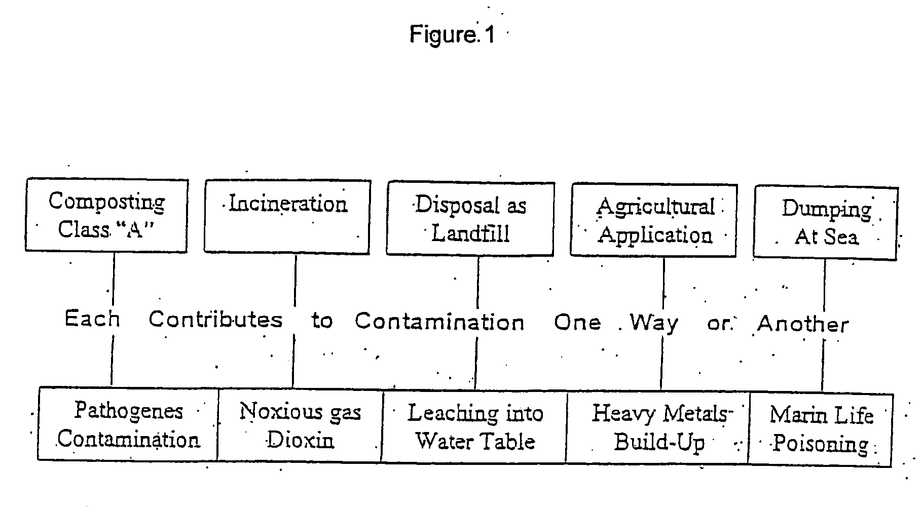
Problems solved by technology

However, the industrial wastes that are present in sewage cause highly toxic materials such as industrial solvents, heavy metals, and even nuclear waste to be left behind in sludge.
In addition the bacteria still alive are pathogenic and may contaminate soils and subsequently ground water.
Disposal of the sludge is expensive and normally constitutes up to 50% of the total annual costs of wastewater treatment.
Furthermore, increasing sludge disposal costs and diminishing landfill capacities are continually driving interest in sludge drying.
Drying process is highly energy consuming and hence very expensive.
One of the major problems in direct solid fuels liquefaction processes is the separation of solids, mineral matter and unconverted organic matter from liquefaction products.
Difficulties in removing these solid components represent a major obstacle to economic production of liquefied feedstocks products.
The removal of the micron-sized particles is difficult to achieve.
However, centrifuges wear out quickly when used for the separation of the micron-sized particles.
Filters are rapidly clogged by the fine material and have to be changed frequently, thereby making the process tedious and costly.
The main shortcoming of the separation methods mentioned above is that none of them ensures complete separation of the liquid products from the solid residue: 25-40% wt of the oil obtained in the liquefaction process remains absorbed in the pores of the solid residue.
It is not always possible to remove sufficient water mechanically and the thus-dried material is fed first into a pre-reactor into which is passed hot separated solids removed from the flue gases from the main fluidized bed reactor, these hot solids being mixed thoroughly with the sludge in the pre-reactor to heat and dry it before it passes to the main reactor.
A practical problem with many of the processes proposed and employed hitherto, particularly those involving pyrolysis and incineration, is that the principal usable energy-containing products are gases, often not easily condensable, and of low net energy content, so that they are impossible or uneconomic to store and must be used immediately.

Method used


Image

  • Process for treatment of organic waste
  • Process for treatment of organic waste
  • Process for treatment of organic waste

Examples


Embodiment Construction

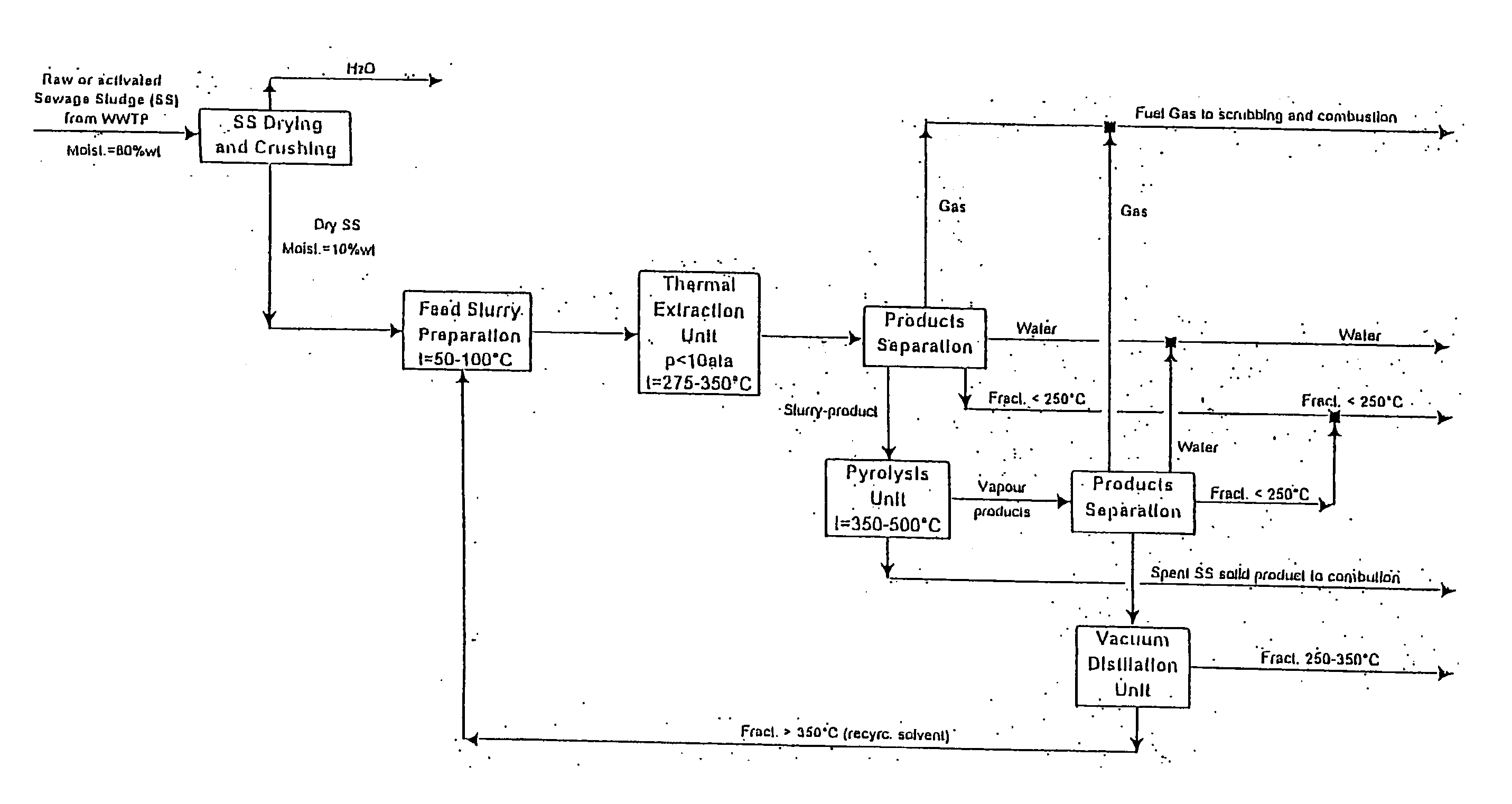
[0057] For purposes of this invention sewage sludge liquefaction is conducted in two separate stages: the first stage is thermal extraction in a recirculating solvent medium wherein said solvent performs several functions:

[0058] Formation of slurry, which facilitates the pumping of the feed stock through the apparatus;

[0059] Improvement of the heat transfer from the heating agent to the feed stock;

[0060] Hydrogen donation in order to recombine the radical fragments formed during the thermal destruction of organic molecules in the feed stock;

[0061] Dissolution of the resulting fragments in the liquefaction medium.

[0062] The presence of the recirculating solvent thus makes for a higher yield of liquid products compared with the processes of pyrolysis known in the literature (see previous section), and for a lower temperature of the treatment (pyrolysis at 4500 C-5500 C, thermal extraction at 2500 C-3500 C for sewage sludge).

[0063] The slurry product obtained at the first stage a...


PUM

PropertyMeasurementUnit
pressureaaaaaaaaaa
temperatureaaaaaaaaaa
boiling temperatureaaaaaaaaaa

Abstract

The invention provides a multi-stage process for the treatment of organic waste comprising drying said waste to reduce the water content to below 15%; subjecting said dried waste to a thermochemical liquefaction process in the presence of a recirculating solvent medium at a temperature of about 275° C. to 375° C. and a pressure of up to 10 atmospheres, thereby obtaining gaseous, liquid and solid products; separating the formed slurry product from condensable gas, water and other liquid fractions boiling out at up to 250° C.; transferring said slurry product obtained from thermal extraction from step c to a pyrolysis apparatus and treating the same at a temperature of about 350° C. to 500° C. to cause additional thermal destruction of unconvertible organic matter of feed material and heavy liquid fractions obtained is step c and their evaporation and removal from pyrolysis apparatus; separating vapor products from condensable oil products; vacuum distillation of oil products from step c for the removal of fractions having a boiling temperature of between 250° C. and 350° C.; and recirculating solvent medium for step b.

Description

FIELD OF THE INVENTION [0001] The present invention relates to organic waste disposal technologies, and more specifically, to a multi-stage processing of sewage sludge into synthetic fuel and chemical products by means of a direct thermochemical liquefaction process. BACKGROUND OF THE INVENTION [0002] Sewage sludge is the thick, malodorous slurry left behind in a sewage treatment plant after its load of human and industrial chemical wastes have been bio-chemically treated and the wastewater discharged. [0003] The large amount of human waste in sewage treatment plants means that the sludge contains high concentrations of phosphates and nitrates, desirable components of fertilizer. However, the industrial wastes that are present in sewage cause highly toxic materials such as industrial solvents, heavy metals, and even nuclear waste to be left behind in sludge. When sewage sludge is applied to the fields, both the nutrients and the toxic chemicals are released to the environment. There...

Claims


Application Information

Patent Timeline
Patent Type & Authority Applications(United States)
IPC IPC(8): B01J29/70C02F11/10C10G1/00C10G1/04
CPCC02F11/10C10G1/006C10G1/042Y02W10/40
Inventor PLOPSKI, YAFIM
Owner BIO GASOLINE
Why Eureka
Try Eureka