Optical Module

a technology of optical modules and optical modules, applied in the field of optical modules, can solve the problems of increasing the size of the apparatus using the optical module, lowering the efficiency and adjustment difficulty, and reducing so as to simplify the assembling process, and reduce the size of the optical module

Inactive Publication Date: 2006-07-13
NIPPON SHEET GLASS CO LTD
View PDF3 Cites 11 Cited by
  • Summary
  • Abstract
  • Description
  • Claims
  • Application Information

AI Technical Summary

Benefits of technology

[0045] Preferably, the diffracted light detection device is a photodetector array. The use of this constituent part permits reduction in size of the optical module to thereby make it possible to complete the spectral distributing function in the optical module.
[0046] According to the configuration of the invention, it is possible to provide an optical module in which the diffraction grating can be positioned and mounted only by a mechanical fitting operation without originally very complex adjustment of the mounting position of the diffraction grating.
[0047] Moreover, because a mechanism for aligning the diffracted light detection device is incorporated, the assembling process can be simplified greatly.
[0048] In addition, because it is not necessary to separately provide any special optical element positioning mechanism or any adhesion / fixation space in the housing of the optical module, great reduction in size of the optical module can be achieved.

Problems solved by technology

There is a problem that it is difficult to assemble an optical module.
Accordingly, there is a problem that the size of an apparatus using the optical module is increased.
Although the angle for changing the optical path may be an acute angle or an obtuse angle other than 90°, this case brings lowering of efficiency and difficulty of adjusting because incidence / output on / from the optical element has an inclination angle.
If light is intended to be incident / outgo perpendicularly on / from the optical element, complexity in device configuration and increase in device size are brought because the optical path of propagating light cannot be made in parallel with the board surface.
It is however unnecessary to adjust the optical path changing angle to 90° accurately.
In the opto-electronic hybrid circuit board, a slight difference in optical path causes a large light loss because the beam diameter of light to be used, the core diameter of the light pipe to be coupled, the area of the photodetecting surface of the flat photodetecting element, and so on, are small.
There arises a problem that a complex assembling or producing process is required.

Method used


Image

  • Optical Module
  • Optical Module
  • Optical Module

Examples


example 1

[0101] In Example 1, a transmission-type diffraction grating is used for changing an optical path. As known well, the transmission-type diffraction grating has a spectral distributing function exhibiting different diffraction angles in accordance with wavelengths. Accordingly, an example using such a spectral distributing function in addition to the optical path changing will be described. FIG. 7 shows the case of Example 1 using the optical system according to the invention.

[0102] Example 1 shows a demultiplexing module including an optical fiber 160, a collimator lens 132, a transmission-type diffraction grating 110, a converging lens 130, and a photodetector array 120.

[0103] A planoconvex lens with a diameter of 4 mm and a focal length f of 7.96 mm with respect to a wavelength of 1550 nm is used as each of the collimator lens 132 and the converging lens 130. A deep-groove laminar diffraction grating having an effective area of 4×6 mm and having 900 grooves per mm is used as the...

example 2

[0108] Although the above description has been made on the case where a light demultiplexing module is formed, the same optical system as described above may be used for forming a light multiplexing module as shown in FIG. 8. As for the constituent members of the optical system, the photodetector array in FIG. 7 is replaced with a light-emitting element array.

[0109] In the light-emitting element array 270, four surface light-emitting semiconductor laser elements 272 each having an effective light-emitting surface with a diameter of 50 μm are arranged at intervals of 200 μm. The laser elements emit light beams with wavelengths of 1510 nm, 1530 nm, 1550 nm and 1570 nm respectively. The light beams 55 output from the laser elements 272 respectively are collimated to parallel light beams 56 approximately by a collimating lens 232. The parallel light beams 56 are incident at an incident angle of about 45° on a surface of the diffraction grating. The light beams with the wavelengths diff...

example 3

[0112]FIGS. 9 and 10 show Example 3 according to the invention.

[0113]FIG. 9 is a sectional view taken along the center axis of the optical module according to the invention. The light input device is a collimator having an optical fiber 350, and a collimator lens 330. Light output from an end surface of the optical fiber 350 is collimated to parallel light beams. The parallel light beams are made incident on the transmission-type diffraction grating 10. The collimator is held by a first holding member (collimator holding member) 335. The collimator holding member 335 is cylindrical so that the collimator lens 330 and a ferrule 360 for holding the optical fiber 350 are inserted and held in a hollow portion of the cylinder of the collimator holding member 335. The hollow portion is circular in section and forms an optical path of parallel light flux output from the collimator.

[0114] Light diffracted by the diffraction grating is converged on the photodetecting surface of the photode...


PUM

PropertyMeasurementUnit
inclination angleaaaaaaaaaa
optical path changing angleaaaaaaaaaa
bending angleaaaaaaaaaa

Abstract

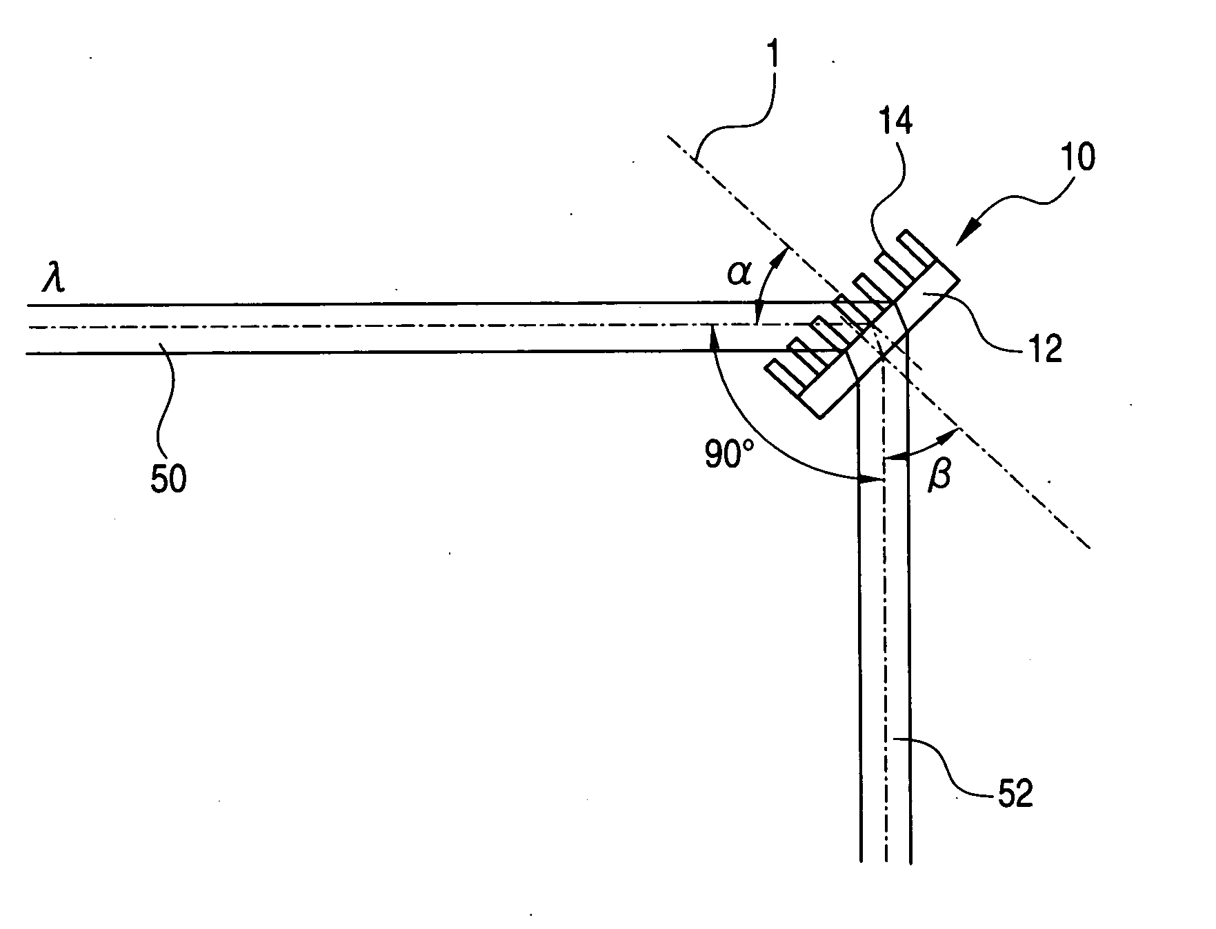
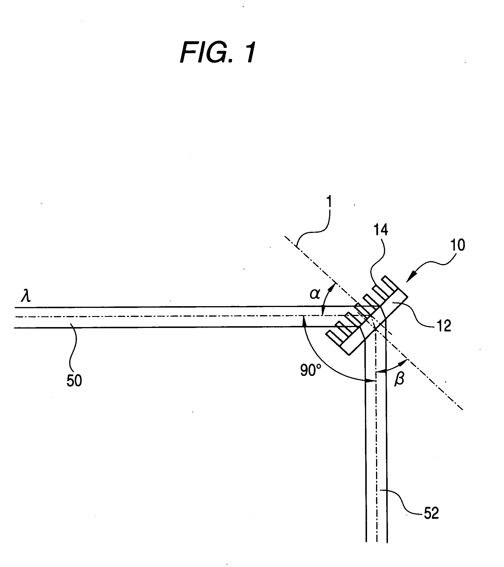
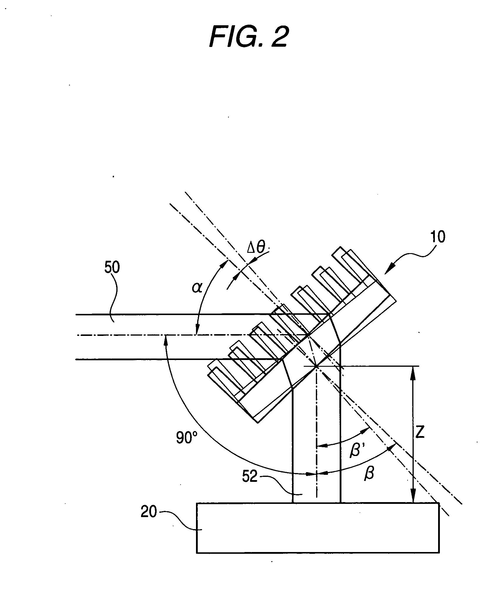
An optical module according to the invention can achieve an optical system using a transmission-type diffraction grating for bending the optical path of incident light with a specific wavelength by about 90°. A substrate of the transmission-type diffraction grating is mounted at an angle in a range of ±5° with respect to the design incident angle α of the incident light. The optical system can be applied to a light multiplexing/demultiplexing module.

Description

BACKGROUND OF THE INVENTION [0001] 1. Field of the Invention [0002] The present invention generally relates to an optical module used in the field of wavelength division multiplexing optical communication technology and in the field of spectrometric technology. One aspect of the invention relates to an optical path changing optical system in an optical module. Further, another aspect of the invention relates to a mechanism for holding optical parts constituting an optical module. 2. Description of Related Art [0003] On the other hand, in the field of spectrometric technology, a diffraction grating is used widely for analyzing spectra of light in a spectrometric apparatus. Spectrometric analysis requires high efficiency in utilization of energy in a wide frequency band. A reflection-type diffraction grating is suitable for obtaining high diffraction efficiency in a wide frequency band. The reflection-type diffraction grating is used widely in a spectrometric apparatus because the ref...

Claims


Application Information

Patent Timeline
Patent Type & Authority Applications(United States)
IPC IPC(8): G11B7/00
CPCG02B5/1871G02B27/1086
Inventor HIKICHI, NAOKONAKAMA, KENICHIARIMA, YASUNORI
Owner NIPPON SHEET GLASS CO LTD
Why Eureka
Try Eureka