Driver assembly for simultaneous axial delivery of spinal implants

a technology of spinal implants and drive shafts, which is applied in the direction of prosthesis, osteosynthesis devices, catheters, etc., can solve the problems of reduced gap between adjacent vertebrae, increased weight of spinal discs, and increased pain, so as to improve weight bearing and load distribution

Active Publication Date: 2006-07-13
MIS IP HLDG LLC
View PDF94 Cites 83 Cited by
  • Summary
  • Abstract
  • Description
  • Claims
  • Application Information

AI Technical Summary

Benefits of technology

[0030] In one aspect of the invention, risks associated with implant expulsion, migration, or subsidence (that are inherently less for the motion preservation assemblies of the present invention) may be even further mitigated by retention means, e.g., by external, self-tapping threads configured to distribute stress evenly over a large surface area, that engage the vertebral body and secure (i.e., anchor) the implant assemblies therein.
[0031] The screw threads are typical of “cancellous” type bone threads known in the art. The threads are typically cut with generally flat faces on the flights of the thread with the most flat of the faces oriented in the

Problems solved by technology

Unfortunately, for a number of reasons referenced below, for some people, one or more discs in the spinal column will not operate as intended.
Often when the discs are not operating properly, the gap between adjacent vertebral bodies is reduced and this causes additional problems including pain.
The spinal discs serve as “dampeners” between each vertebral body that minimize the impact of movement on the spinal column, and disc degeneration, marked by a decrease in water content within the nucleus, renders discs ineffective in transferring loads to the annulus layers.
In addition, the annulus tends to thicken, desiccate, and become more rigid, lessening its ability to elastically deform under load and making it susceptible to fracturing or fissuring, and one form of degeneration of the disc thus occurs when the annulus fissures or is torn.
The fissure itself may be the sole morphological change, above and beyond generalized degenerative changes in the connective tissue of the disc, and disc fissures can nevertheless be painful and debilitating.
Nevertheless, even a contained disc herniation is problematic because the outward protrusion can press on the spinal cord or on spinal nerves causing sciatica.
Another disc problem occurs when the disc bulges outward circumferentially in all directions and not just in one location.
Mechanical stiffness of the joint is reduced and the spinal motion segment may become unstable, shortening the spinal cord segment.
As the disc “roll” extends beyond the normal circumference, the disc height may be compromised, and foramina with nerve roots are compressed causing pain.
Although these procedures are less invasive than open surgery, they nevertheless suffer the possibility of injury to the nerve root and dural sac, perineural scar formation, re-herniation of the site of the surgery, and instability due to excess bone removal.
Although damaged discs and vertebral bodies can be identified with sophisticated diagnostic

Method used


Image

  • Driver assembly for simultaneous axial delivery of spinal implants
  • Driver assembly for simultaneous axial delivery of spinal implants
  • Driver assembly for simultaneous axial delivery of spinal implants

Examples


example a

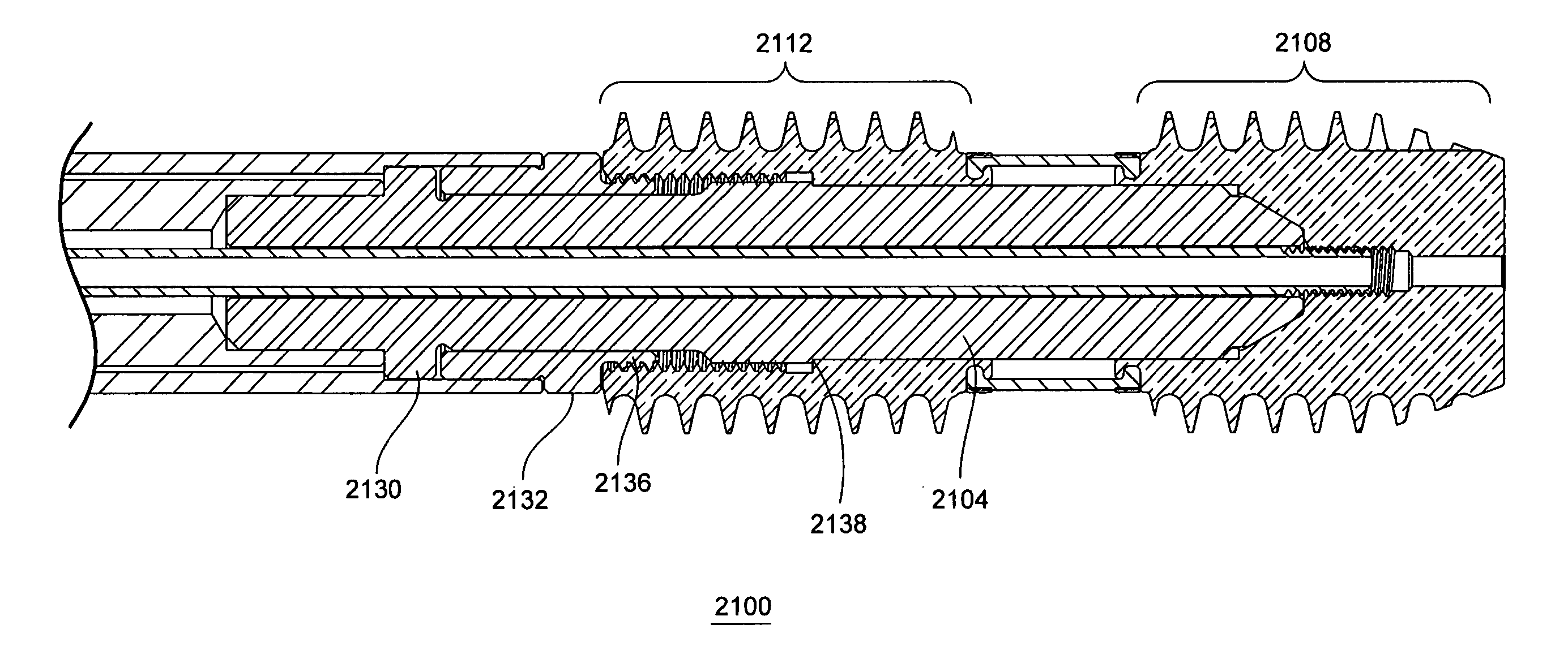
[0081] One solution to the above-identified short comings in the prior art is shown in FIG. 6. FIG. 6A shows an enlarged portion of a loaded dual anchor driver assembly 2100 in a perspective view with a quarter round removed to expose the interaction of components. The dual anchor driver assembly 2100 uses a polygonal torque driver 2104 to simultaneously engage a distal bone anchor 2108 and a proximal bone anchor 2112. These bone anchors have external threaded sections (2116 and 2120) that have the same minor diameter, the same major diameter, the same pitch, and the same handedness. In order to avoid cross threading the helical thread cut left by distal anchor external threads 2116 in the proximal vertebral body as the proximal anchor external threads 2120 are rotated into the proximal vertebral body, the delivery of the two bone anchors must be timed. Having control over the relative position of the bone anchors during the rotation and axial advancement of the bone anchors makes t...

example b

[0087] As shown in FIG. 10, polygonal torque driver 2104 has a hollow cavity 2224 running along its longitudinal axis which is used by the retention rod 2012. This same cavity 2224 could be connected through apertures (not shown) to deliver flowable material between the distal component 2108 and the proximal component 2112 into the intervertebral disc space. A variety of biomaterials can be delivered. Examples include curable elastomers, hydrogels, and blends of elastomers and hydrogels. While the cavity 364 in the distal end of the distal component is open to allow a loaded driver assembly to be deployed over a guide wire, this should not present a problem while injecting material. The opening to the cavity 364 will often be contained within the distal vertebral body (See FIG. 3). However, the retention rod or some other delivery device could be used to deliver a plug to this cavity 364 after it has served its purpose with respect to the guide wire.

example c

[0088]FIG. 17 shows an alternative torque driver 2230 with apertures 2234. A dual hex head driver 2230 of this type is adapted for use when the cross section of the distal component is reduced relative to the cross section of the proximal component such as illustrated in FIG. 5B, typically when dissimilar thread pitch is being used to provide distraction. After distraction, a driver assembly using the dual hex head driver 2230 can be left in place, that is with the driver maintaining the relative position of the two components as one component is held by engagement with the distal portion of the dual hex head driver 2230 by the retention rod and the other component is held in engagement with a more proximal portion of the dual hex head driver by the coupling. FIG. 18A provides an exploded diagram showing the use of an O-Ring to help limit the undesired flow of injected material into the driver assembly. FIGS. 18B and 18C illustrate other details of the interaction between the dual h...


PUM

PropertyMeasurementUnit
Lengthaaaaaaaaaa
Flow rateaaaaaaaaaa
Distanceaaaaaaaaaa

Abstract

Tools for use in the deployment of spinal implant assemblies such as spinal motion preservation assemblies adapted for use in a spinal motion segment are disclosed including the process for delivering and assembling the spinal motion preservation assemblies in the spinal motion segment via an axial channel created with a trans-sacral approach. The tools allow the deployment of a pair of spinal implant components that are not rigidly connected to one another to be driven into adjacent vertebral bodies. The tools further allow for distraction via either dissimilar thread pitch or by axially advancing a distraction tool based on a threaded engagement with a proximal component in a proximal vertebral body to impose an distraction between that vertebral body and an adjacent distal vertebral body. The tools also allow for the provision of flowable biomaterials such as prosthetic nucleus material. Delivery of flowable biomaterials can be performed while the vertebrae are being held apart by a distraction tool.

Description

BACKGROUND OF THE INVENTION [0001] This application claims priority and incorporates by reference a co-pending and commonly assigned U.S. Provisional Application No. 60 / 621,730 filed Oct. 25, 2004 for Multi-Part Assembly for Introducing Axial Implants into the Spine. This application claims priority and incorporates by reference both U.S. patent application Ser. No. 11 / 256,810 filed Oct. 24, 2005 for Spinal Motion Preservation Assemblies (Attorney Docket No. T105002USU) and a U.S. Provisional Application No. 60 / 621,148 filed Oct. 22, 2004 for Spinal Mobility Preservation Assemblies. This application claims priority and incorporates by reference four co-pending and commonly assigned U.S. patent application Ser. Nos. 10 / 972,184, 10 / 927,039, 10 / 972,040, and 10 / 972,176 all filed on Oct. 22, 2004. These four applications claim priority to two provisional application 60 / 558,069 filed Mar. 31, 2004 and 60 / 513,899 filed Oct. 23, 2003. Priority to these two provisionals is claimed through th...

Claims


Application Information

Patent Timeline
IPC IPC(8): A61F2/34
CPCA61B17/025A61B17/3421A61B17/7055A61B17/8888A61B17/8897A61B2017/00261A61B2017/0256A61B2017/3445A61F2/30742A61F2/441A61F2/4425A61F2/4455A61F2/4611A61F2/4637A61F2002/30075A61F2002/30235A61F2002/30327A61F2002/30405A61F2002/30495A61F2002/30507A61F2002/3055A61F2002/30563A61F2002/30566A61F2002/30581A61F2002/30588A61F2002/30601A61F2002/30649A61F2002/30665A61F2002/3085A61F2002/30859A61F2002/30863A61F2002/443A61F2002/444A61F2002/4627A61F2002/4629A61F2210/0061A61F2220/0025A61F2230/0069A61F2250/0039A61B17/58A61F2/44
Inventor AINSWORTH, STEPHEN D.ASSELL, ROBERT L.WESSMAN, BRADLEY J.
Owner MIS IP HLDG LLC
Why Eureka
Try Eureka