Cylinder liner and cylinder block

a technology of cylinder block and liner, which is applied in the direction of cylinders, reciprocating piston engines, positive displacement engines, etc., can solve the problems of increased fuel consumption, reduced performance, gap or void formation at the interface between the cylinder block main body, etc., and achieves easy measurement or judgment, easy deburring, and further improvement of the bonding strength between the two.

Active Publication Date: 2006-07-20
SUBARU CORP +1
View PDF10 Cites 15 Cited by
  • Summary
  • Abstract
  • Description
  • Claims
  • Application Information

AI Technical Summary

Benefits of technology

[0019] It is therefore a first object of the present invention to provide a cylinder liner which controls gap formation at the interface between the cylinder liner and a cylinder block main body for accepting the cylinder liner therein, and serves to obtain stable contacting state and excellent bonding strength between the cylinder liner and the cylinder block main body.
[0022] In the above-mentioned cylinder liner, it is preferable that each of the grooves further comprises a second inclination part extending from the groove bottom part, the second inclination part opposing the first inclination part and extending in a direction away from the center of the cylinder liner in an axial direction thereof By the provision of the second inclination part, it is possible to form a proper undercut area in the grooves. Accordingly, the contacting state between the cylinder liner and the cylinder block, and the bonding strength therebetween are further improved. The grooves in the form of a spiral is continuously formed by placing a workpiece of a cylinder liner on a lathe, bringing a blade tool into contact with the outer surface of the workpiece, and moving the blade tool in a longitudinal direction of the workpiece.
[0023] It is also preferable that the cylinder liner having the groove in the form of a spiral further comprises a ringshaped central gain on the outer surface of the cylinder liner, the central gain extending in a circumferential direction of the cylinder liner at the center of the cylinder liner in an axial direction thereof, the central gain at least partially overlapping with the groove formed closely to the center of the cylinder liner in an axial direction thereof. The provision of the central gain makes it easy to measure or judge the manufacturing condition of the groove such as the depth of the groove and makes it easy to perform deburring.
[0024] It is a second object of the present invention to provide a cylinder block wherein a gap is not formed at the interface between the cylinder liner and a cylinder block main body for accepting the cylinder liner therein, and which has stable contacting state and excellent bonding strength between the cylinder liner and the cylinder block main body.
[0027] In the above-mentioned cylinder block, it is preferable that each of the grooves in the cylinder liner comprises a second inclination part extending from the groove bottom part, the second inclination part opposing the first inclination part and extending in a direction away from the center of the cylinder liner in an axial direction thereof. Accordingly, the contacting state between the cylinder liner and the cylinder block, and the bonding strength therebetween are further improved.
[0028] It is also preferable that the cylinder liner having the groove in the form of a spiral, which is provided in the cylinder block, further comprises a ring-shaped central gain on the outer surface of the cylinder liner, the central gain extending in a circumferential direction of the cylinder liner at the center of the cylinder liner in an axial direction thereof the central gain at least partially overlapping with the groove formed closely to the center of the cylinder liner in an axial direction thereof. The provision of the central gain makes it easy to measure or judge the manufacturing condition of the groove such as the depth of the groove and makes it easy to perform deburring.

Problems solved by technology

However, it is possible that, in the production by a conventional cylinder block having a cylinder liner, gaps or voids are formed at the interface between the cylinder block main body and the cylinder liner.
As a result, engine oil consumption and abrasion of the piston ring are increased, and hence this can be a cause of increased fuel consumption, decrease of performance, and short life of the engine.
In this case, the cylinder liner can corrode, and the corrosion may lead to deformation of the cylinder liner.
When the gap is formed at the interface between the cylinder block main body and the cylinder liner, the load is applied non-uniformly to the cylinder liner.
Accordingly, elastic deformation, that is, spring-back of the cylinder liner occurs, and a cylinder block is manufactured with decreased accuracy.
Likewise, when the cylinder block main body is processed by a machine, a load is applied non-uniformly to the cylinder block around the gap.
Accordingly, it is difficult to manufacture a cylinder block with good accuracy.
Therefore, it is possible that an aluminum alloy cylinder block main body is damaged.
In particular, a part of the cylinder block main body with a small thickness may be damaged when the stress is concentrated in the part.
On the other hand, the bond strength between the cylinder block main body and the cylinder liner is low.
Therefore, the cylinder liner tends to be affected by stress such as residual stress or shrinkage generated by the solidification of the melt of the aluminum alloy used for casting.
Consequently, it is difficult to obtain a regularly formed interface between the cylinder block main body and the cylinder liner.
On the other hand, however, the grooves or the protrusions in the form of stripes hinder the flow of the melt of the aluminum alloy.
Moreover, there are limitations for forming a plurality of protrusion on the outer surface of the cylinder liner by the treatment by a machine, and it is possible that the manufacturing cost is increased.
As a result, a layer with non-uniform thickness is obtained from the metal compound.
Consequently, irregular interfaces are formed, and the interface may have a gap and unstable bonding strength.

Method used


Image

  • Cylinder liner and cylinder block
  • Cylinder liner and cylinder block
  • Cylinder liner and cylinder block

Examples


first embodiment

[0055] FIGS. 1 to 10 describe a first embodiment of a cylinder liner and a cylinder block according to the present invention.

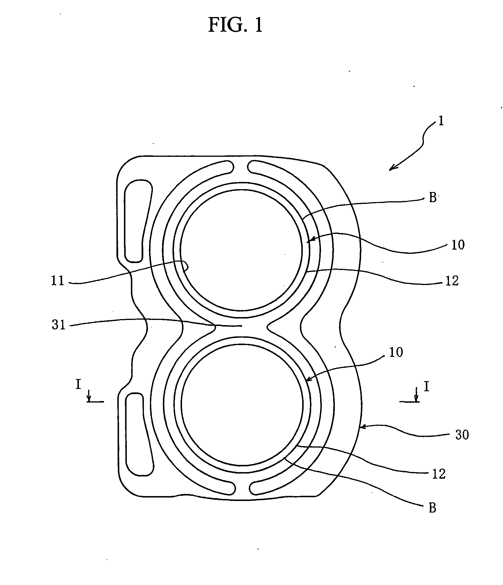
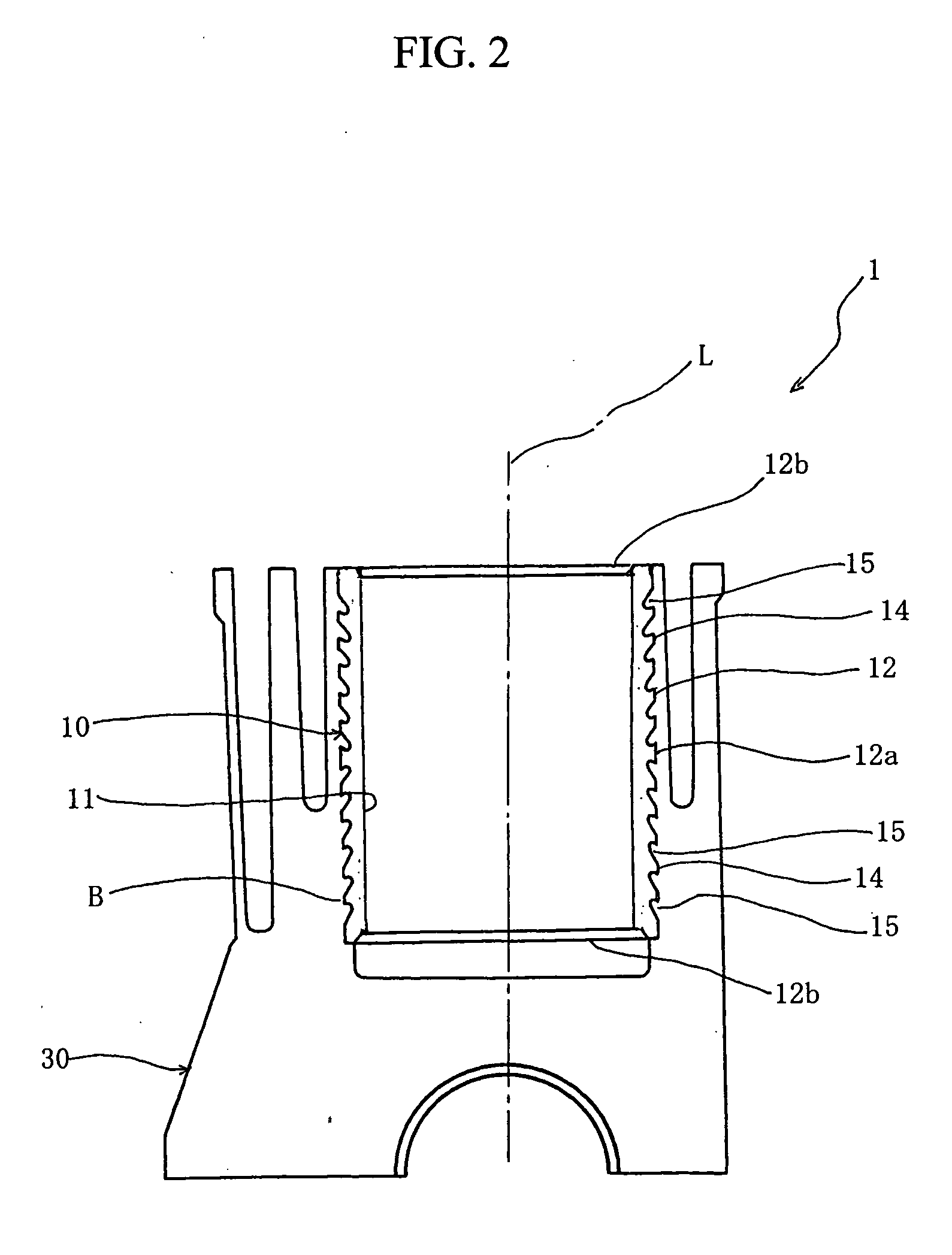
[0056]FIG. 1 is a plane view of a cylinder block 1 including a cast iron cylinder liner 10 provided in an aluminum alloy cylinder block main body 30 by casing the aluminum alloy. FIG. 2 is a cross-section of the cylinder block 1 shown in FIG. 1 obtained by cutting along a line I-I therein. FIG. 3 is a perspective view of the cylinder liner 10, FIG. 4 is a side view of the cylinder liner 10, and FIG. 5 is an expanded cross-sectional view of the cylinder liner 10 shown in FIG. 3 which is obtained by cutting along a line I-II in FIG. 3.

[0057] As shown in FIGS. 3 to 5, the cylinder liner 10 has a cylindrical shape, extending in a direction of a central axis L. The cylinder liner 10 has a cross-section in the form of a circle drawn around the central axis L. The cylinder liner 10 has an inner surface 11 and an outer surface 12.

[0058] A plurality of grooves 15 ar...

second embodiment

[0074] FIGS. 11 to 23 describe a second embodiment of a cylinder liner 20 and a cylinder block 1 according to the present invention.

[0075]FIG. 11 is a perspective view of a cast iron cylinder liner 20 according to the present invention. FIG. 12 is an expanded cross-sectional view of the cylinder liner 20 shown in FIG. 11 which is obtained by cutting along a line III-III therein.

[0076] As shown in FIGS. 11 and 12, the cylinder liner 20 has a cylindrical shape, extending in a direction of a central axis L. The cylinder liner 20 has a cross-section in the form of a circle drawn around the central axis L. The cylinder liner 20 has an inner surface 21 and an outer surface 22.

[0077] Grooves 25 are formed on the outer surface 22 of the cylinder liner 20. The grooves 25 extend in the form of a spiral having a plurality of turns in a circumferential direction R of the cylinder liner 20. By the provision of the grooves 25 with a spiral shape, the outer surface 22 of the cylinder liner 20 i...

example 1

[0099] Cast iron cylinders with inner diameter of 100 mm, outer diameter of 106 mm, and length in the axial direction of 120 mm were used as workpieces. The outer surfaces of the workpieces were carved by a carving tool having a nose angle of 35° and a corner radius of 0.4 mm, so that cylinder liners 20 having spiral grooves 25 having a depth of 0.7 mm were prepared. For comparison, cylinder liners 20 were formed with different cutting edge angles and different pitch sizes. Each of the cylinder liners 20 was used for a die-cast aluminum alloy cylinder block main body 30, so that a cylinder block 1 was formed. The contacting state at the interface between the cylinder liner 20 and the cylinder block main body 30, and the productivity of the cylinder block 1 were evaluated.

[0100] FIGS. 21 and FIG. 22 show the test result. More precisely, FIG. 21is a table for showing the relationship among the cutting edge angle, pitch of the spiral section, productivity of the cylinder liner 20, and...


PUM


Abstract

A cast iron cylinder liner of the present invention includes a plurality of grooves formed on an outer surface of the cylinder liner. Each of the grooves extends in a circumferential direction of the cylinder liner in a ring or spiral shape, and the grooves divide the outer surface of the cylinder liner into a plurality of ring or spiral sections. The outer surfaces of the ring sections have a uniform distance from the central axis of the cylinder liner over the entire area of the outer surfaces, and the grooves being arranged symmetrically with respect to the center of the cylinder liner in an axial direction thereof. Each of the grooves has a J-shaped longitudinal cross-section including a first inclination part and a groove bottom part. The first inclination part extends from the outer surface of one of the ring sections or of one turn of the spiral sections toward the center of the cylinder liner in an axial direction thereof. The groove bottom part has a longitudinal cross-section approximately in the form of a circular arc, and extends from the first inclination part in a direction away from the center of the cylinder liner in an axial direction thereof

Description

CROSS REFERENCE TO RELATED APPLICATIONS AND INCORPORATION BY REFERENCE [0001] This application is based upon and claims the benefit of priority from the prior Japanese Patent Application No. 2005-008103, filed on Jan. 14, 2005; the entire content of which is incorporated herein by reference. BACKGROUND OF THE INVENTION [0002] 1. Field of the Invention [0003] The present invention relates to a cylinder liner and a cylinder block having a cast cylinder liner therein to be used for an engine. [0004] 2. Discussion of the Related Art [0005] A widely-used cylinder block for an engine is made of an aluminum alloy for decreasing the weight thereof and achieving low fuel consumption. For producing an engine having a good abrasive resistance, a cast iron cylinder liner is provided on the inner surface of a cylinder block main body. [0006] However, it is possible that, in the production by a conventional cylinder block having a cylinder liner, gaps or voids are formed at the interface between ...

Claims


Application Information

Patent Timeline
Patent Type & Authority Applications(United States)
IPC IPC(8): F16J10/00F01B11/02F02F1/10
CPCF02F1/004F02F1/18
Inventor ODA, TERUYUKINOZAWA, TSUYOSHIKOYAMA, KAZUO
Owner SUBARU CORP
Why Eureka
Try Eureka