
Nucleation method for atomic layer deposition of cobalt on bare silicon during the formation of a semiconductor device

a technology of atomic layer deposition and semiconductor devices, which is applied in the direction of chemical vapor deposition coating, coating, basic electric elements, etc., can solve the problems of increasing the resistance of the feature, increasing the thickness of the material layer being deposited, and difficult to deposit films in the bottom of a deep feature having a high aspect, depth to width ratio,

Active Publication Date: 2006-07-20
MICRON TECH INC
View PDF2 Cites 46 Cited by
  • Summary
  • Abstract
  • Description
  • Claims
  • Application Information

AI Technical Summary

Benefits of technology

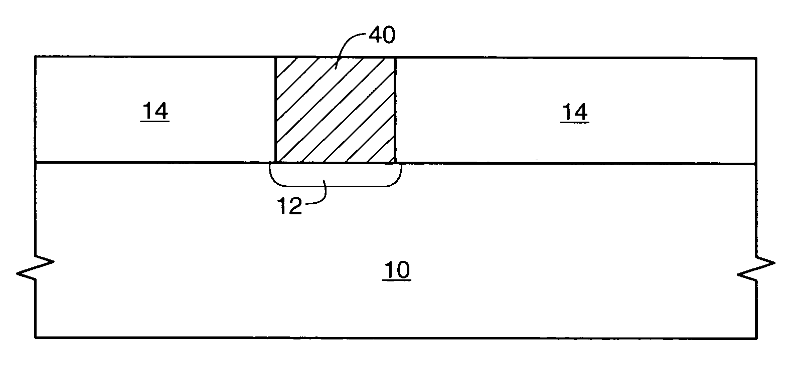
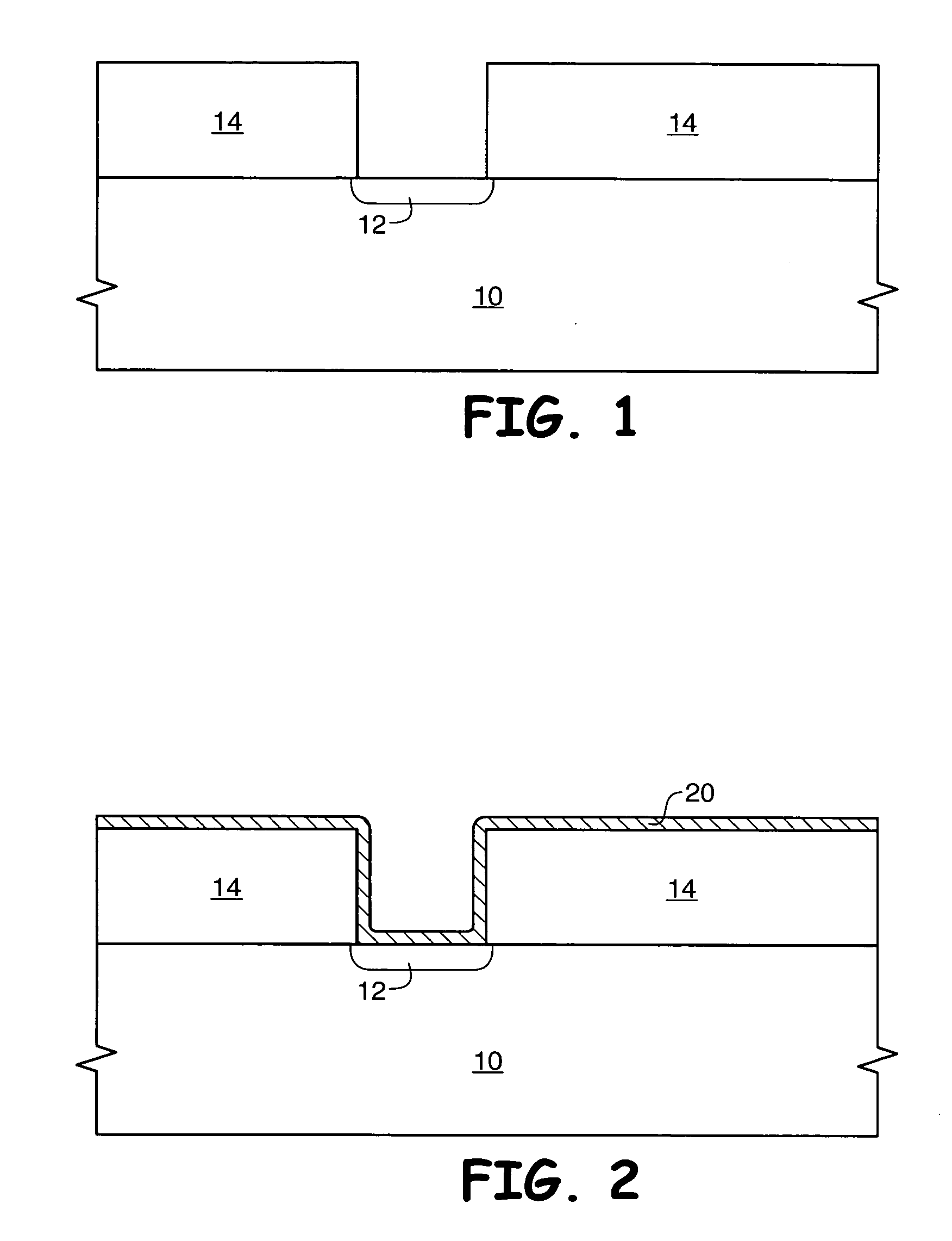
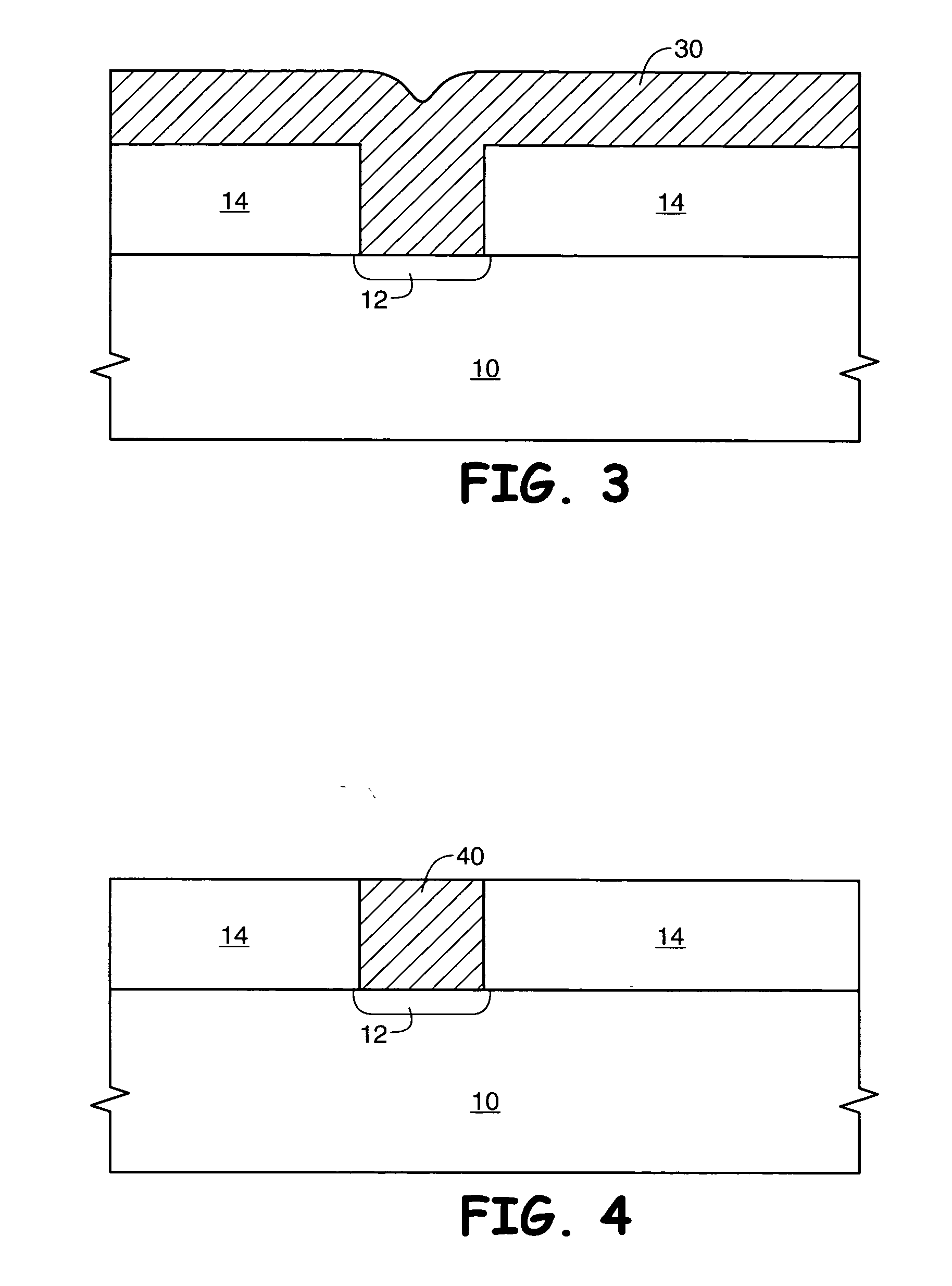
The present invention provides a method of forming a layer of cobalt metal on bare silicon using an atomic layer deposition process. The method involves cleaning the silicon surface, exposing it to a tantalum nitride precursor or titanium nitride precursor, purging the chamber, and then introducing a cobalt precursor. The exposed silicon is then exposed to ammonia to produce a cobalt metal layer that acts as a nucleation layer for further cobalt formation. The cobalt metal layer can be patterned and etched or annealed to form a desired feature on the silicon surface. The invention allows for the formation of a semiconductor device with a layer of cobalt metal on a bare silicon surface, which can be used in various applications such as forming a cobalt silicide feature or a cobalt metal layer covering a polysilicon feature.

Problems solved by technology

One problem resulting from smaller feature sizes is that decreasing the width of a conductive line or conductive plug decreases the cross-sectional area of the line or plug, which in turn increases the resistance of the feature.
Both sputtering and CVD result in the continued increase in thickness of the material layer being deposited during the process.
Since the deposition process is line-of-sight, it is difficult to deposit films in the bottom of a deep feature having a high aspect, or depth to width, ratio.
However, the formation of pure metal cobalt on bare silicon, for example by exposing bare silicon to a cobalt precursor, has not proven possible.
Oxide / oxygen formation has deleterious effects, for example increasing the resistance between the silicon wafer and a cobalt / cobalt silicide contact.

Method used


Image

  • Nucleation method for atomic layer deposition of cobalt on bare silicon during the formation of a semiconductor device
  • Nucleation method for atomic layer deposition of cobalt on bare silicon during the formation of a semiconductor device
  • Nucleation method for atomic layer deposition of cobalt on bare silicon during the formation of a semiconductor device

Examples


Embodiment Construction

[0019] The term “wafer” is to be understood as a semiconductor-based material including silicon, silicon-on-insulator (SOI) or silicon-on-sapphire (SOS) technology, doped and undoped semiconductors, epitaxial layers of silicon supported by a base semiconductor foundation, and other semiconductor structures. Furthermore, when reference is made to a “wafer” in the following description, previous process steps may have been utilized to form regions or junctions in or over the base semiconductor structure or foundation. Additionally, when reference is made to a “substrate assembly” in the following description, the substrate assembly may include a wafer with layers including dielectrics and conductors, and features such as transistors, formed thereover, depending on the particular stage of processing. Further, in the discussion and claims herein, the term “on” used with respect to two layers, one “on” the other, means at least some contact between the layers, while “over” means the laye...


PUM

PropertyMeasurementUnit
depthaaaaaaaaaa
pressureaaaaaaaaaa
pressureaaaaaaaaaa

Abstract

A method used to form a cobalt metal layer on a silicon surface using an atomic layer deposition (ALD) process comprises a treatment of the silicon surface prior to cobalt formation. Treatment includes serial exposure to one or more cycles comprising a titanium nitride precursor or a tantalum nitride precursor, followed by an optional exposure to ammonia. After this treatment, the silicon surface is exposed to a metal organic cobalt such as cyclopentadienylcobalt dicarbonyl to form a cobalt precursor on the silicon surface, which is then exposed to hydrogen or ammonia to reduce the precursor to an ALD cobalt metal layer. Once this initial metal layer is formed, additional cobalt ALD layers may be completed to form a cobalt metal layer of a desired thickness.

Description

FIELD OF THE INVENTION [0001] This invention relates to the field of semiconductor manufacture and, more particularly, to a method for forming a pure metal cobalt layer on a bare, clean silicon surface using atomic layer deposition. BACKGROUND OF THE INVENTION [0002] During the manufacture of semiconductor devices such as dynamic random access memories, static random access memories, logic devices, and microprocessors, several structures are commonly formed. For example, conductive interconnects such as word lines, and conductive plugs such as digit line contact plugs, are commonly used. [0003] A common engineering goal during the design of semiconductor devices is to manufacture as many features in a given area as possible. An obvious method to aid in accomplishing this goal is to make feature sizes smaller. One problem resulting from smaller feature sizes is that decreasing the width of a conductive line or conductive plug decreases the cross-sectional area of the line or plug, wh...

Claims


Application Information

Patent Timeline
Patent Type & Authority Applications(United States)
IPC IPC(8): H01L23/48H01L21/4763
CPCC23C16/0272C23C16/18C23C16/45529C23C16/45553H01L21/28562
Inventor MARSH, EUGENE P.
Owner MICRON TECH INC
Learn More