

Chemical mechanical polishing compositions for metal and associated materials and method of using same
a technology of mechanical polishing compositions and metals, applied in the direction of polishing compositions with abrasives, manufacturing tools, lapping machines, etc., can solve the problems of significant copper dishing on the surface of semiconductor wafers, step coverage problems, and/or dielectric erosion, etc., to achieve high removal rate, low removal rate, and high removal rate
- Summary
- Abstract
- Description
- Claims
- Application Information
AI Technical Summary
Benefits of technology
Problems solved by technology
Method used
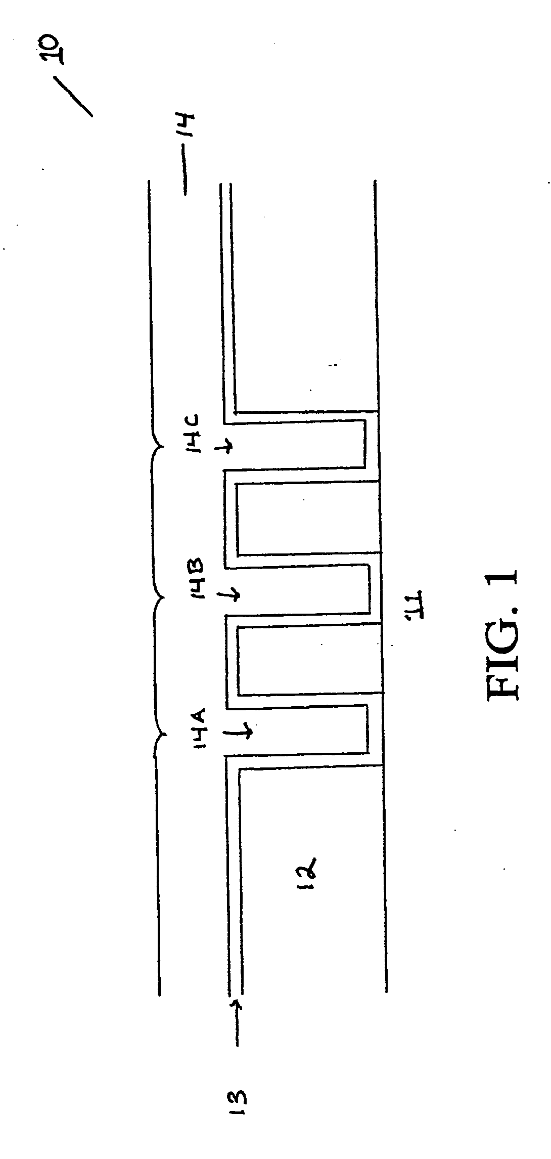
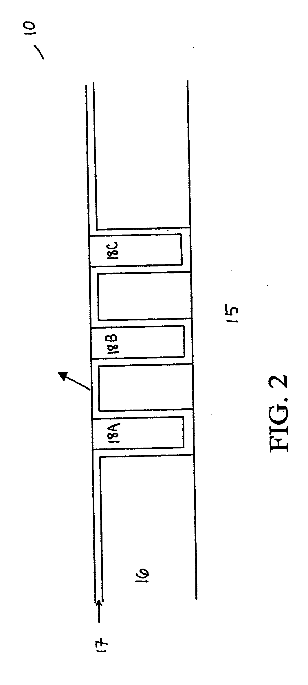
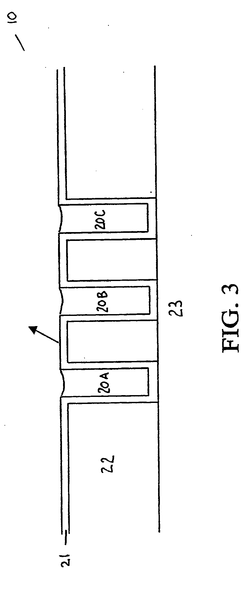
Image

Examples
example 1
Slurry 1 Formulations Showing Static Etch Rate of Copper
[0083] Several formulations of the first slurries were prepared. The static etch removal rates of these formulations are described in Table 2. As can be seen from Table 2, the first step slurry formulations of the present invention were effective in achieving acceptable static copper removal rates of 50 Å / min
TABLE 2 Removal Rate Under Static Conditions (SRR). Component Values in Weight PercentCitricSRRSlurryH2O2AcidIDAAbrasiveNH3pH{acute over (Å)}150.22.5300(2)250.12.6237(2)3554.1208(5)45152N / A(5)550.252.3N / A(5)6510.22.11600(2)944(3)7510.252.2N / A(5)80.550.002733.51.17(1)950.50.005233.5661(1)1050.20.002983.7150(1)90(2)1150.50.20.008913.5640(1)501(3)1250.550.005293.5793(1)1350.250.0033.6149(1)98(2)70(5)1450.50.250.008853.5858(1)627(2)453(5)15100.50.250.009123.51029(1)578(2)468(5)439(10)1610.50.250.008513.5855(1)666(2)563(5)520(10)1750.250.550.013.5601(1)488(2)450(5)1850.25150.0173.5836(1)561(2)377(5)1950.250.550.443.5960(1)504...
example 2
[0084] Table 3 outlines twelve formulations and polishing conditions for the second step polishing slurry tested on Ta, TaN, Cu and thermal oxide blanket wafers (Table 4). The various formulations comprise between 0 to 13 percent hydrogen peroxide (H2O2) as oxidizing agent, 0 to 0.05 percent ethylenediamine as complexing agent, between 0 to 0.1 percent BTA, or between 0 to 0.2 percent iminodiacetic acid as passivating agent, and between 5 to 10 percent colloidal silica or 5 to 10 percent precipitated silica. The pH of the formulations ranged from 6.8 to 8.8. The polishing conditions ranged from table speed (TS) of 45 to 125 rpm, quill speed (QS) of 42 to 116 rpm, down force (DF) of 3.5 to 4 psi, and a flow rate (FR) of 160 mL / min.
TABLE 3 Compositions and Polishing Conditions for Second Step SlurryColloidalPrecipitatedPolish ConditionsSlurry:H2O2EDABTAIDASilicaSilicaKOHpHTS / QS / DF / FR10.0558.8125 / 116 / 4.0 / 16025*6.8125 / 116 / 4.0 / 16030.50.0556.845 / 42 / 3.5 / 160413108.1125 / 116 / 4.0 / 1605130.210...
example 3
Stability Experiment
[0087] The poly (methyl methacrylate) colloid of the step one slurry formulation shows outstanding chemical and mechanical stability. The particles did not show any significant changes in terms of particle size and particle size distribution after aging two months, that is, the mean particle size remains about 45 nm and the range of distribution is from about 5 nm to 100 nm.
PUM
| Property | Measurement | Unit |
|---|---|---|
| particle size distribution | aaaaa | aaaaa |
| thick | aaaaa | aaaaa |
| particle size distributions | aaaaa | aaaaa |
Abstract
Description
Claims
Application Information