Dynamic journal engine

a journal engine and engine technology, applied in the direction of positive displacement engines, bearings, shafts and bearings, etc., can solve the problems of increasing complexity and incorporating difficult geometries, and previous attempts to achieve the same sort of improvement over the simple crank shaft have displayed a remarkable degree of complexity, and achieve the effect of efficient energy conversion

Active Publication Date: 2006-07-27
JOHNSON MELISSA T
View PDF3 Cites 5 Cited by
  • Summary
  • Abstract
  • Description
  • Claims
  • Application Information

AI Technical Summary

Benefits of technology

[0011] An additional benefit of this design is the elimination of the wrist pin that connects rod to piston in a traditional crankshaft engine. An even more important reduction in parts associated with this improved geometry is that multiple piston engines are able to eliminate the need for a separate contoured set of plates connecting them to the output shaft. Each piston / rod / follower pin can use the same contoured plates that ordinarily would be used by a single piston. Thus a two cylinder engine would be able to reduce total parts by four, a three cylinder by eight, a four cylinder by twelve, etc. Finally, the need for a lubrication gallery machined through the rod of a conventional crankshaft engine for the purpose of lubrication the wrist pin is obviously eliminated.
[0012] The relative worth of the Dynamic Journal Engine concept, therefore, is measurable by its relative simplicity of concept and operation and the consequent manufacturing / maintenance costs, and its more efficient conversion of energy in relationship to torque produced in the case of an engine.

Problems solved by technology

Previous attempts to effect this same sort of improvement over the simple crank shaft have displayed a remarkable degree of complexity.
Albeit, their concept of utilizing mechanical devices that avail themselves at an advantageous point in time to the rapid detonation in a cylinder suffer from the serious drawback of increased complexity incorporating difficult geometries such as sliding ellipses, sinusodial shafts passing through slotted rods, multiple rollers following the path of an epitrochoidal drum, etc.
Further, the contoured distance of the orbital path from the center of the output shaft are subject to the requirements of the engine's function, i.e., the desire for high rpm or high torque.

Method used


Image

  • Dynamic journal engine
  • Dynamic journal engine
  • Dynamic journal engine

Examples


Embodiment Construction

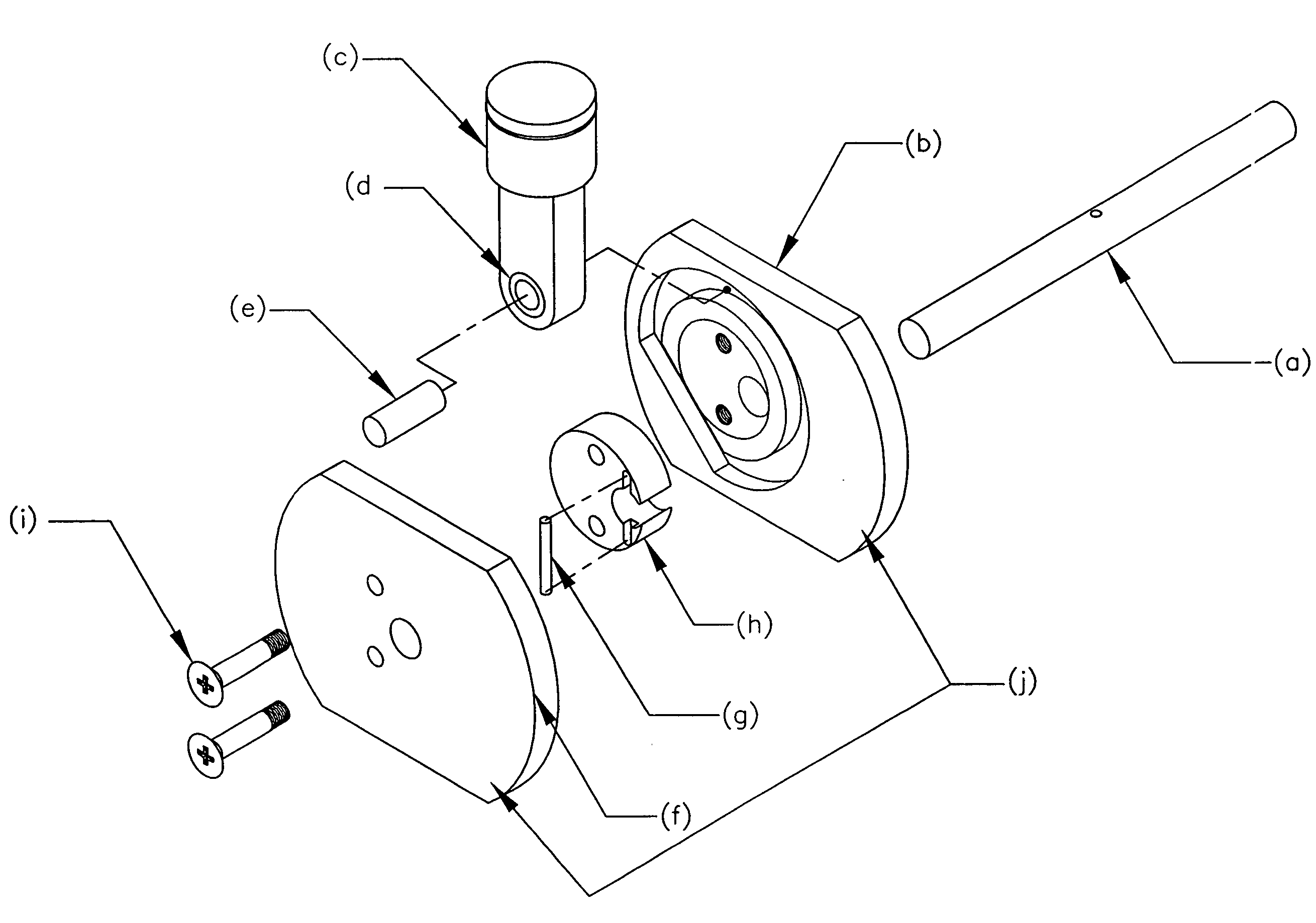
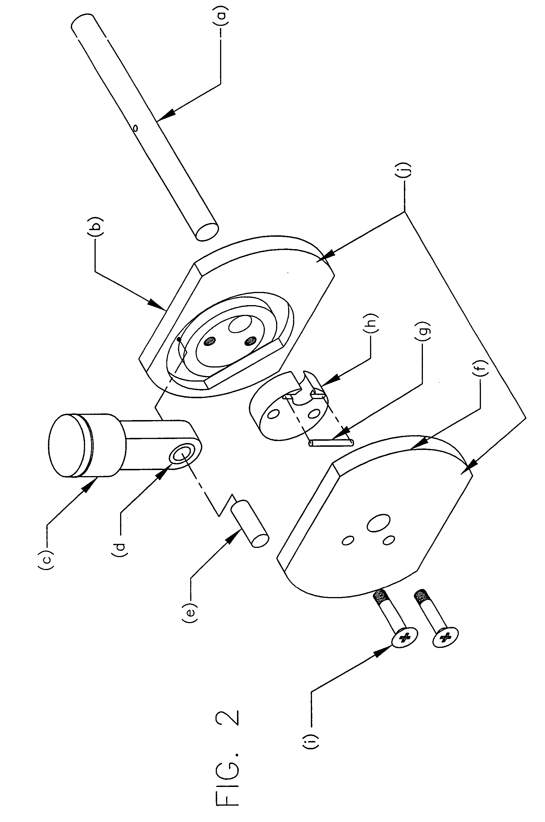
[0024] With reference to the figures, 1 is a depiction of a generic cylinder, piston / rod, bearing, pin, one mirrored image plate with contour, output shaft and crankcase with an improvement on the translation of reciprocating motion to circular motion by incorporating a dynamic journal.

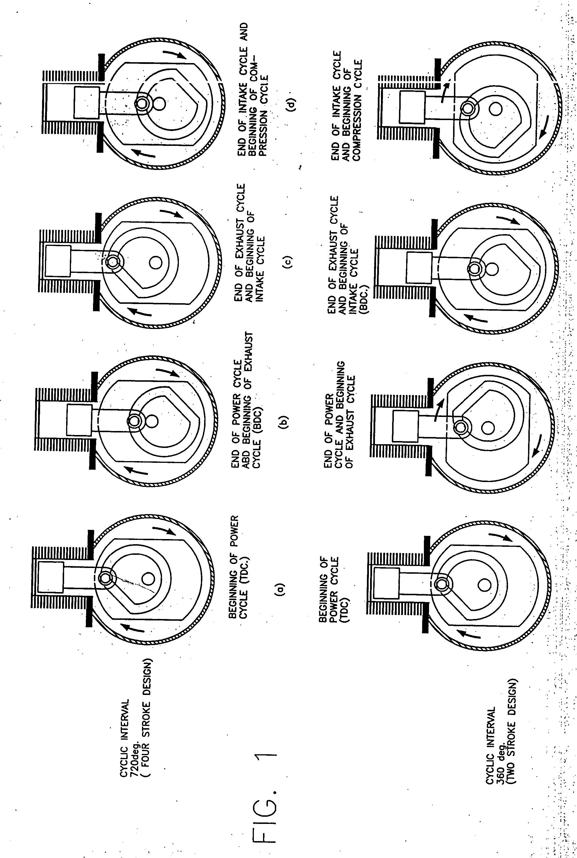
[0025] The cylinder in FIG. 1(a) is closed at one end providing a head for the working fluid to expand against the head itself thus translating the moveable piston / rod, bearing, pin in an opposite linear direction.

[0026] The pin in the bearing in the rod opposite the piston face is depicted in the contour of the plate in FIG. 1(a) at the initiation of the power cycle whereby thermodynamic pressure on the piston crown opposite the cylinder head causes linear motion to be transmitted to said pin which rotates in said bearing creating positive translation of said linear motion to the rotating motion of said contoured plates.

[0027] The contoured plate in FIG. 1(b), (c), (d), imparts inertial force to s...


PUM


Abstract

An internal combustion engine that replaces the throw journal of a crankshaft with a set of contours that are dynamic rather than static. The contour is such that three cycles of engine operation are not affected, i.e., exhaust, intake, and compression. The contour deviates only during the power stroke where an increased incidence to the circular is incorporated. This defers from previous attempts by eliminating complex geometries such as epitrochoidal or sinusoidal that by their nature negatively affect the exhaust, intake, and compression strokes of the Otto cycle when compared to the traditional crankshaft. Additionally, the deviation from the circular orbit during the power cycle optimizes to a larger extent the leverage available for peak thermodynamic pressures in the cylinder in the brief optimum time afforded by that pressure.

Description

BACKGROUND OF THE INVENTION [0001] 1. Field of the Invention [0002] The invention is relative to internal combustion engines which are in present use for transportation, manufacturing, electrical power production, agriculture, forestry, lawn maintenance, and compressors in common use for applications including heating and air conditioning, refrigeration, and inflation. [0003] Internal combustion engines currently used are of two basic designs: Otto cycle or Brayton cycle. Piston engines incorporate a sequential division of a 360 or 720 degree circle roughly segmented in four cycles or strokes. Brayton (turbine) engines perform the same cycles but are continuous in those cycles because of a constant pressure design. [0004] The operation of reciprocating internal combustion engines follows this sequence: the intake stroke, comprising roughly one fourth of the rotation, permits the introduction of combustibles, i.e., fuel and air. The compression stroke, covering again roughly one four...

Claims


Application Information

Patent Timeline
Patent Type & Authority Applications(United States)
IPC IPC(8): F02B75/22F02B75/24F02B75/32
CPCF02B75/00F02B75/32F01B9/026F01B9/06
Inventor JOHNSON, MICHAEL ELMAN
Owner JOHNSON MELISSA T
Why Eureka
Try Eureka