
Electromagnetic shielding sheet, front plate for display, and method for producing electromagnetic shielding sheet

a technology front plate, applied in the field can solve the problems of inability to effectively use metal meshes, inability to suppress, and inability to meet the requirements of electromagnetic shielding sheet provided with a thin film of a transparent conductor, and achieve the effect of high production efficiency and high yield

Active Publication Date: 2006-07-27
DAI NIPPON PRINTING CO LTD
View PDF0 Cites 17 Cited by
  • Summary
  • Abstract
  • Description
  • Claims
  • Application Information

AI Technical Summary

Benefits of technology

[0014] The present invention has been made to solve those problems and it is therefore an object of the present invention to provide an electromagnetic shielding sheet capable of being accurately fabricated by a small number of steps at high yield, of intercepting electromagnetic waves generated by a display when disposed on the front surface of the display and of making images displayed by the display satisfactorily visible, a method of manufacturing the electromagnetic shielding sheet, and a front sheet for a display.
[0016] The electromagnetic shielding sheet according to the present invention capable of intercepting electromagnetic waves, not absorbing image light emitted by a display and capable of preventing the reduction of the brightness of a displayed image due to illumination by external light can be manufactured without increasing steps of a manufacturing process or reducing yield.
[0020] The electromagnetic shielding sheet according to the present invention disposed on the front surface of a display is capable of effectively intercepting electromagnetic waves generated by the display.
[0022] The electromagnetic shielding sheet prevents the formation of moiré, absorbs unnecessary visible light of specific wavelengths and / or near-infrared radiation and improves the visibility of images displayed by the display.
[0024] The electromagnetic shielding sheet manufacturing method according to the present invention is capable of forming a laminated structure of a good quality including a uniform adhesive layer not containing many bubbles, needs a single cycle of the blackening treatment, and is capable of forming the mesh metal film without breaking the component lines of the mesh metal film and of producing the electromagnetic shielding sheet at high production efficiency and high yield.

Problems solved by technology

But the shielding members used by those methods are opaque and hence are not suitable for suppressing the radiation of electromagnetic radiation from displays, such as CRTs and PDPs.
There have not been any metal meshes capable of effectively dealing with electromagnetic shielding, infrared shielding and visibility improvement, to say nothing of metal meshes capable of providing electromagnetic shielding and visibility improvement on a practical level.
However, the electromagnetic shielding sheet provided with a thin film of a transparent conductor cannot deal with both electromagnetic shielding and transparency.
The metal meshes (lines) of all the electromagnetic shielding sheets fabricated by the methods mentioned in Patent documents 1 to 5 are not sufficiently dark and are unable to make displayed images clearly visible in a place illuminated by external light.
However, since the blackened surface is roughened by the blackening treatment, an unsatisfactory adhesive film, such as an irregular adhesive film or an adhesive film containing bubbles, is formed to spoil the quality of the laminated sheet.
Thus this method is troublesome and reduces yield.

Method used


Image

  • Electromagnetic shielding sheet, front plate for display, and method for producing electromagnetic shielding sheet
  • Electromagnetic shielding sheet, front plate for display, and method for producing electromagnetic shielding sheet
  • Electromagnetic shielding sheet, front plate for display, and method for producing electromagnetic shielding sheet

Examples


example 1

[0109] A 10 μm thick electrolytic copper foil having a surface roughness Rz of 2 μm for forming a metal film 21 was bonded to a 100 μm thick polyethylene terephthalate film (PET film A4300, Toyobo) for forming a transparent base sheet 11 with a polyurethane adhesive layer 13 to form a laminated web. The laminated web was aged at 50° C. for three days. The polyurethane adhesive layer 13 was prepared by mixing a polyol (Takerakku A-310, Takeda Yakuhin Kogyo) as a chief ingredient and isocyanate (A-10, Takeda Yakuhin Kogyo) as a hardener. The dry thickness of the adhesive layer 13 was 4 μm.

[0110] The copper foil of the laminated web was processed by a photolithographic process to form a mesh foil as explained below. The laminated web was subjected continuously to a masking process and an etching process on an existing color TV shadow mask manufacturing line. The copper foil of the laminated web was coated with a positive photoresist, namely, casein, by a flow coating method to coat th...

example 2

[0113] An electromagnetic shielding sheet in Example 2 was fabricated by the same method as that of fabricating the electromagnetic shielding sheet in Example 1, except that the former method used a mixed plating bath prepared by mixing a copper sulfate solution of 85 g / l copper sulfate concentration, a cobalt sulfate solution having of 15 g / l cobalt sulfate concentration and a sulfuric acid solution of 120 g / l sulfuric acid concentration.

example 3

[0114] An electromagnetic shielding sheet in Example 3 was fabricated by the same method as that of fabricating the electromagnetic shielding sheet in Example 1, except that the former method used a mixed plating bath prepared by mixing a copper sulfate solution of 85 g / l copper sulfate concentration, a nickel sulfate solution having of 15 g / l nickel sulfate concentration and a sulfuric acid solution of 120 g / l sulfuric acid concentration.


PUM

PropertyMeasurementUnit
Transparencyaaaaaaaaaa
Reflectionaaaaaaaaaa

Abstract

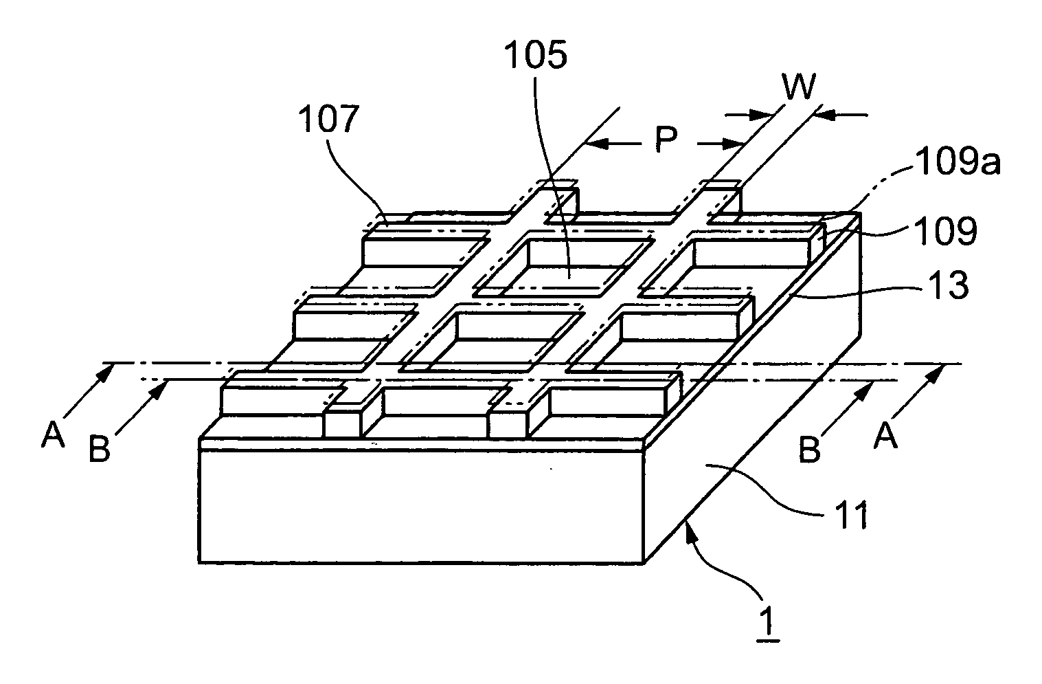
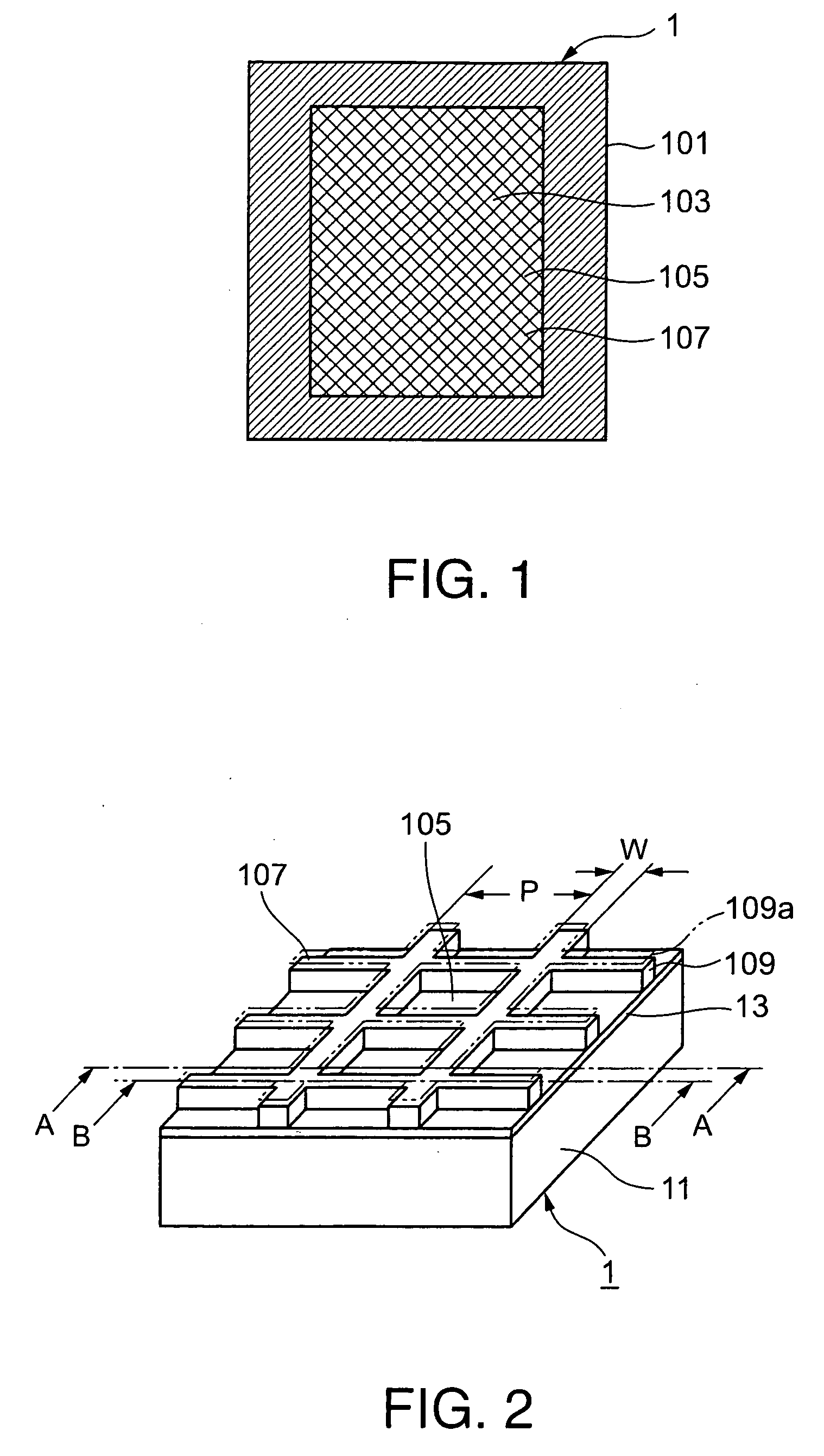
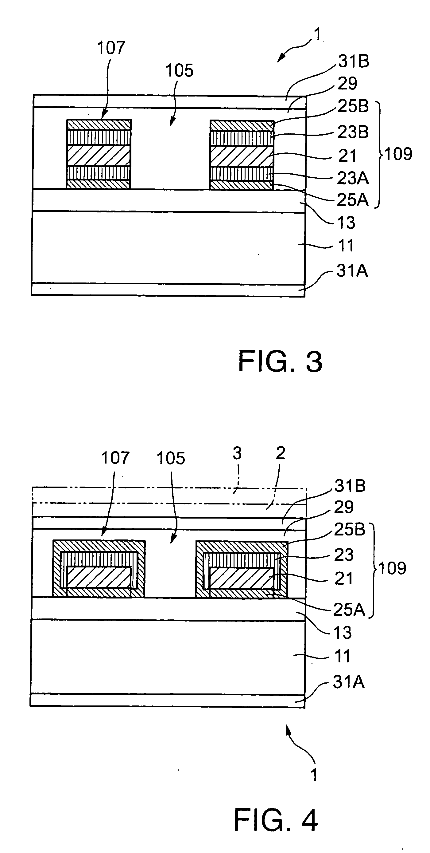
A metal film 21 is laminated directly to or by means of an adhesive 13 to a transparent base sheet 11. A mesh metal film including lines defining apertures is formed by coating the metal film 21 with a mesh resist layer 109a patterned in a mesh, etching the metal film 21 through the mesh resist layer 109a, and removing the mesh resist layer 109a. The front surfaces and side surfaces of the lines of the mesh metal film are coated with a black coating layer 23.

Description

TECHNICAL FIELD [0001] The present invention relates to an electromagnetic shielding sheet and more specifically, to an electromagnetic shielding sheet provided with a metal (thin film) mesh, to be disposed on the front surface of a display, such as a CRT (cathode-ray tube) or a PDP (plasma display panel), to intercept electromagnetic waves emitted by the display and to insure the satisfactory visual recognition of images displayed by the display, a method of manufacturing the electromagnetic shielding sheet, and a front sheet for a display. BACKGROUND ART [0002] Problems caused by electromagnetic interference (EMI) have increased with the functional advancement and the prevalent use of electric and electronic devices. Electromagnetic noises are classified roughly into conduction noises and radiation noises. A conduction noise elimination method uses a noise filter. One radiation noise elimination method uses a metal case for electromagnetically isolating a space, another radiation ...

Claims


Application Information

Patent Timeline
IPC IPC(8): C23F1/00B32B5/00B32B3/24B32B7/02B32B15/08G09F9/00H05K9/00
CPCB32B3/30Y10T428/24B32B15/02B32B15/08B32B15/09B32B15/20B32B27/36B32B2255/06B32B2255/205B32B2255/26B32B2307/412B32B2307/42B32B2457/20B32B2571/00H01J2211/446H01J2329/869H05K9/0096B32B7/12H05K9/00
Inventor ARAKAWA, FUMIHIROISHII, YASUHIKOHASHIMOTO, DAISUKEKYOUDEN, YUKIHIROOISHI, EIJI
Owner DAI NIPPON PRINTING CO LTD
Learn More