Solid oxide fuel cell assembly with replaceable stack and packet modules

Inactive Publication Date: 2006-07-27
CORNING INC
View PDF18 Cites 78 Cited by
  • Summary
  • Abstract
  • Description
  • Claims
  • Application Information

AI Technical Summary

Benefits of technology

[0019] According to another aspect of the present invention a method of repairing a fuel cell system which includes a plurality of fuel cell stacks comprises a step

Problems solved by technology

The fracture of ceramic bodies due to sudden temperature changes and temperature gradients within the bodies is a major failure mode for ceramic materials.
A large fraction of the cost of an SOFC systems resides in the extensive peripheral or supporting systems required for the efficient operation of the advanced core items, i.e., the cells themselves.
Much of the cost of the stack is due to non-active cell components such as insulation, piping, plates, etc.
In a typical planar SOFC design, if an individual cell plate fails, replacement of the cell plate is difficult due to permanent nature of the interconnections between the cells and the bipolar interconnects within the stack.
One disadvantage of chromium steel alloys in fuel cells is the tendency of the chromium to act as a “poison”

Method used


Image

  • Solid oxide fuel cell assembly with replaceable stack and packet modules
  • Solid oxide fuel cell assembly with replaceable stack and packet modules
  • Solid oxide fuel cell assembly with replaceable stack and packet modules

Examples


example 1

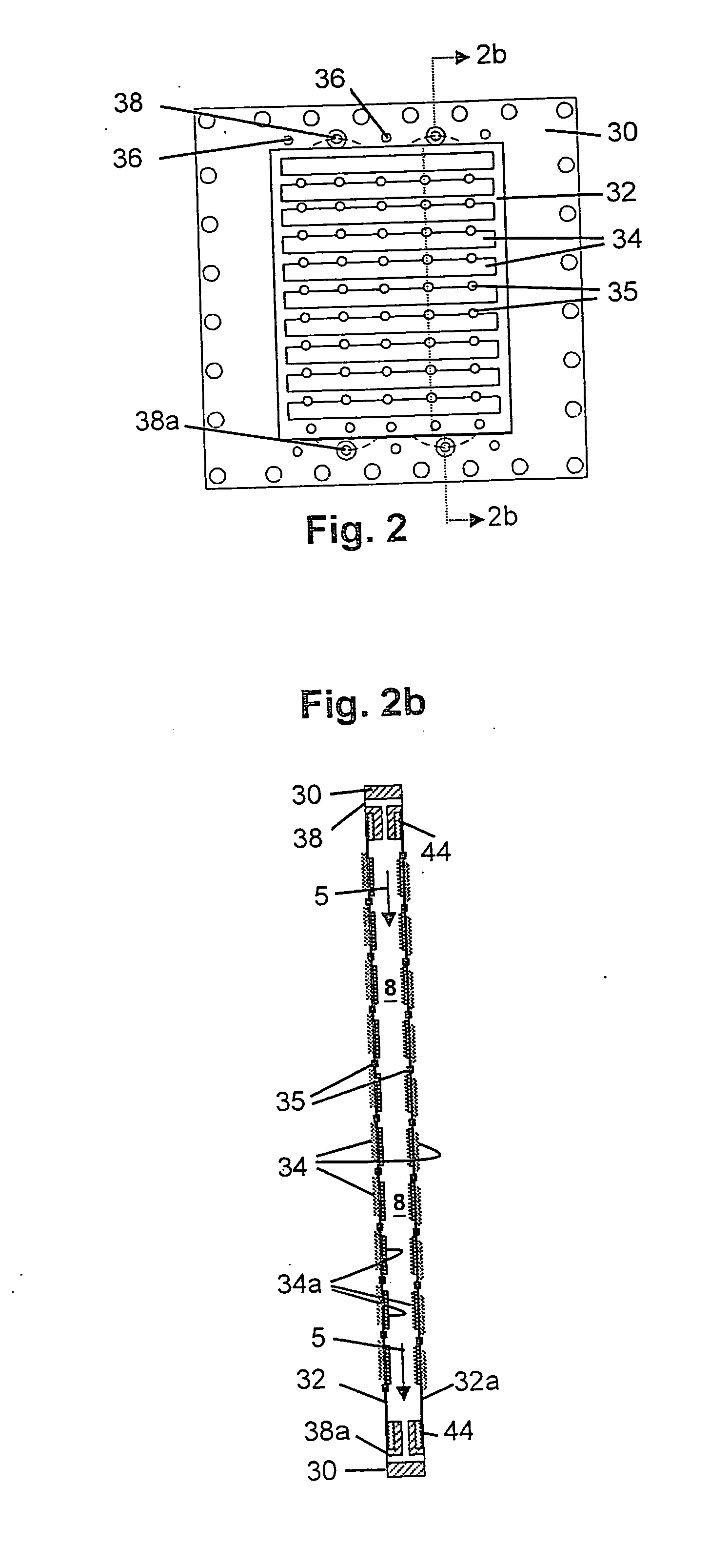
[0158] A framed packet assembly for use in a fuel cell stack is constructed from steel framing members and multi-cell-sheet devices in accordance with a stack assembly design substantially similar to that illustrated in FIGS. 6-11 of the drawings. First prepared are 3 / 16″-thick frames of Type 446 stainless steel, these frames being machined to provide a fuel packet frame and a pair of air frames incorporating inlet channels, orifices and air or fuel chambers substantially as described.

[0159] To the machined fuel frame thus provided are next attached a pair of multi-cell-sheet devices. The devices selected for this attachment consist of flexible 12 cm by 15 cm electrolyte sheets of 3 mol % Y2O3-partially-stabilzed ZrO2 composition provided with a total of 540 via holes. Onto the first or anode sides of each of these sheets are deposited arrays of 10 anodes, each consisting of 6-micron-thick Ni / ZrO2 catalyst layers and 20-micron-thick layers of ceramic-powder-filled 90% Ag / 10% Pd sil...

example 2

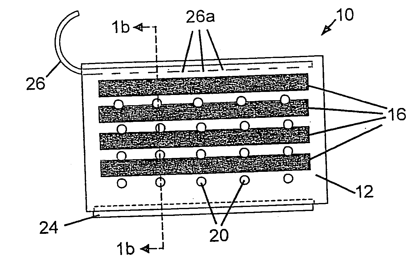
[0169] A four-cell packet incorporating a partially stabilized zirconia (zirconia —3 mole % yttria) electrolyte support sheet, similar in configuration to the packet depicted in FIG. 1 of the drawings, is first provided. With reference to FIG. 1, to provide this packet 10 a first pre-sintered zirconia—3 mole % yttria electrolyte sheet 12 of approximate dimensions 10 cm×6 cm and supporting 4 pairs of silver / palladium alloy electrodes 16-16a is fastened to the top edge of a second pre-sintered zirconia—3 mole % yttria electrolyte sheet 14 as a backing sheet. Fastening is by means of an edge seal 18 formed from a 70:30 (parts by weight) of 230 Duralco:954 Durabond cement mixture, a commercially available material.

[0170] Each alloy electrode pair 16-16a attached to the first sheet includes an interior fuel electrode or anode 16a and an exterior air electrode or cathode 16, these being in largely overlapping positions on opposing sides of the sheet. Each of these electrodes is approxima...

example 3

[0176] An eight-cell packet comprising 8 anode-cathode pairs with each electrode having a width of about 3 mm and a length of about 8 cm is prepared as described in Example 1. The electrolyte support sheet consists of a flexible zirconia—3 mole % yttria ceramic sheet about 25 micrometers in thickness. To increase the surface roughness of the sheet for reduce electrode interfacial resistance, a thin film of yittria-stabilized zirconia nano-crystals is applied to the surface of the sheet by spraying the sheet with a yttria-zirconia sol while heating the sheet on a hot plate.

[0177] The electrodes are applied to the surfaces of the thus-coated sheet by silk-screening, being formed of the zirconia-filled silver-palladium alloy employed in Example I. Vias through the sheet for the series interconnection of the electrode pairs as in Example I are formed of the same silver palladium alloy.

[0178] A flexible packet backing sheet formed of zirconia—3 mole % yttria ceramic is then provided, t...


PUM


Abstract

A method of replacing a fuel cell packet module in a fuel cell stack, said method comprising: (i) powering down the fuel cell stack; (ii) electrically disconnecting the fuel cell packet module from external power load, (iii) mechanically disconnecting the fuel cell packet module from the fuel cell stack; and (iv) removing the fuel cell packet module from the stack.

Description

[0001] This application is a CIP from U.S. application Ser. No. 10 / 277,563 filed on Oct. 21, 2002, which claims the benefit of, and priority to, U.S. Provisional Application Nos. 60 / 332,521, filed Nov. 21, 2001, entitled “Packet Design for Solid Oxide Fuel Cell”, and 60 / 406,518, filed Aug. 27, 2002, entitled “Solid Oxide Fuel Cell Stack and Packet Designs”, both by Badding et al, the content of which is relied upon and incorporated herein by reference in its entirety.BACKGROUND OF THE INVENTION [0002] The present invention relates to solid oxide fuel cells (SOFCs) and more particularly to designs for SOFCs wherein the electrical power generating elements comprise one or a plurality of replaceable self-contained packets connected to means for introducing gaseous fuel to the interiors of the packets. [0003] A large number of tubular SOFC designs are known. These include long and / or flattened tube designs such as proposed by Siemens AG, zirconia tubes with banded stripes on them to for...

Claims


Application Information

Patent Timeline
IPC IPC(8): H01M8/12H01M8/24H01M8/02
CPCH01M8/0271H01M8/0273H01M8/242H01M8/2425H01M8/2475H01M2008/1293Y02E60/50Y02E60/525H01M8/2432H01M8/2428H01M8/2484H01M8/24H01M8/04H01M8/04303
Inventor BADDING, MICHAEL EDWARDST JULIEN, DELL JOSEPHKETCHAM, THOMAS DALE
Owner CORNING INC
Why Eureka
Try Eureka