Mold and process for making a very thin wall article

a molding process and very thin wall technology, applied in the field of plastic molding, can solve the problems of affecting the strength of molded parts, the speed at which they can be produced, the energy requirements of temperature control and other factors, and the inability to meet the requirements of molten materials, so as to facilitate the flow of molten materials and reduce the injection pressure. , the effect of increasing the thickness of the flow path

Inactive Publication Date: 2006-08-03
THERMAL WAYE MOLDING
View PDF2 Cites 9 Cited by
  • Summary
  • Abstract
  • Description
  • Claims
  • Application Information

AI Technical Summary

Benefits of technology

[0024] An object of the invention is to provide a mold defining a mold cavity and a process to fill the mold cavity, for a very thin walled article, by relying on temperature control aspects to extend the time that the mold cavity remains unobstructed to as to permit further flow of the melt. According to another aspect, however, the mold and process for manufacture of a very thin disc can include use of a thickened center portion. The thickened center portion facilitates starting the molten material flowing into the cavity due to the increased flow path thickness in that area. Therefore, the injection pressure required to fill the center portion of the disc is less than when the center portion is thinner.
[0025] Another object of the invention is generally to accomplish mold coining at lower injection pressures than known heretofore. Coining techniques involve injecting the melt at an injec...

Problems solved by technology

The relative thickness versus elongation of an article to be injection molded using heated plastic resins or the like, can cause molding challenges and design constraints.
Tradeoffs that are made in molding very thin wall articles can affect the strength of the molded parts, their surface quality, cost, the speed at which they can be produced, the energy requirements for temperature control and other factors.
Some of the problems and choices that are encountered concern arrangements by which heat energy is transferred from the heated molding material into the mold cavity.
It is undesirable for this process to take any longer than absolutely necessary.
For example, if the mold cavity is kept at a higher temperature during filling, it takes a long time for the molded part to set.
If the material composition is arranged to have a particularly low viscosity, the surface or strength qualities of the part may be less than adequate.
A very high injection pressure can be used to fill the mold very quickly, but that causes other design and operational problems.
Due to these issues, thin wall parts are molded at high melt temperature, very high injection pressure, and high injection rates.
In fact it has not been practical or possible to date to dependably mold the approximately 0.3 mm thick middle layer disc to the required quality needed for DVD-14 and DVD-18 described by...

Method used


Image

  • Mold and process for making a very thin wall article
  • Mold and process for making a very thin wall article
  • Mold and process for making a very thin wall article

Examples


first embodiment

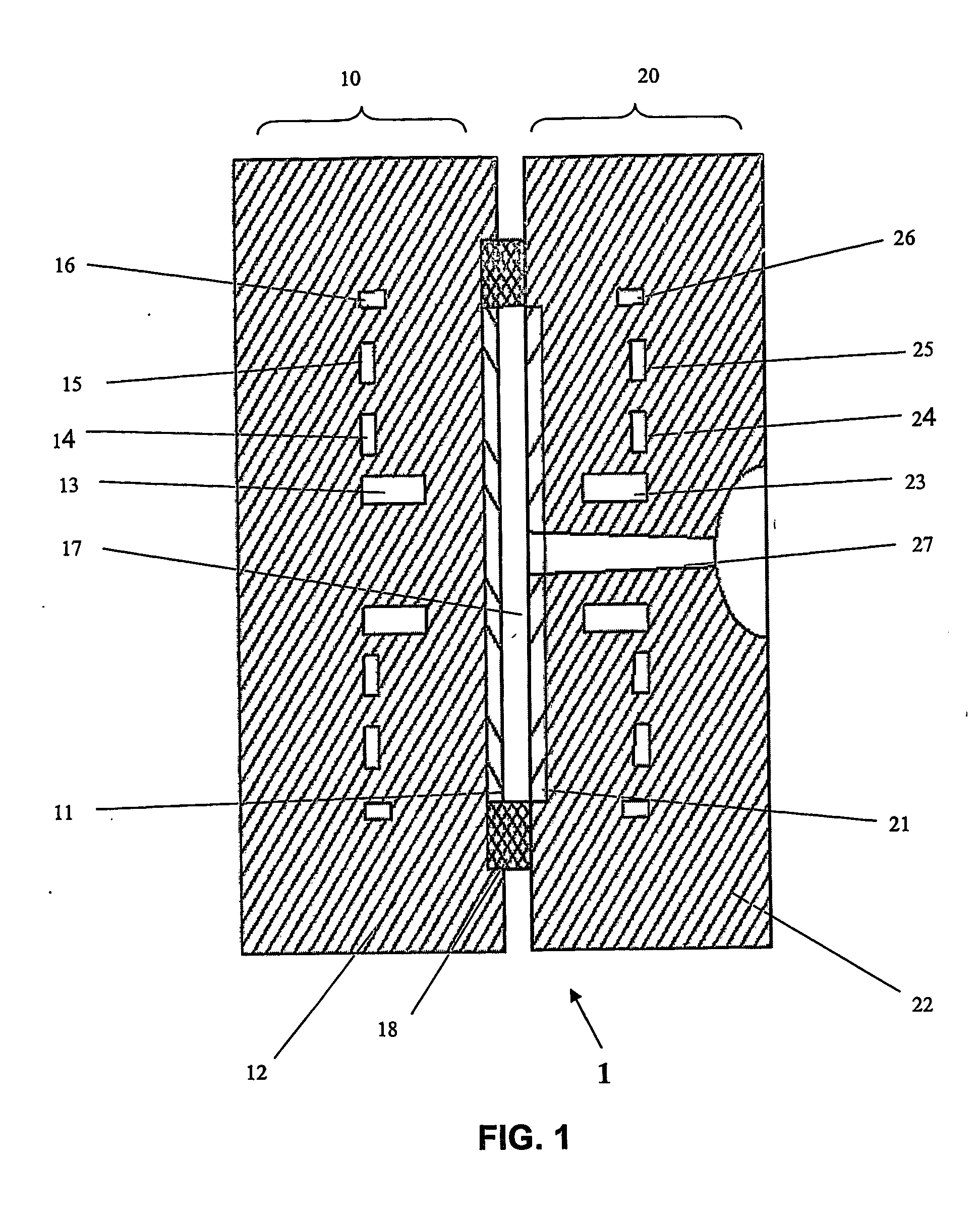
[0050] In accordance with a preferred embodiment of the invention, there is disclosed in FIG. 1 a simplified cross-section of a first embodiment mold 1 for manufacturing a very thin wall optical disc. This embodiment is discussed in connection with a moving mold part 10 and an opposed mold part 20, it being understood that such movement is a relative matter and either or both of the mold parts can be movable. The disclosed embodiment is more or less symmetrical across the cavity, each side having thermally insulating temperature boosters and temperature control fluid passages. It should also be understood that the preferred symmetrical arrangement is only an example and it is also possible to embody the invention asymmetrically, e.g., with temperature boosters on one side only.

[0051] In the embodiment of FIG. 1, a relatively movable side element 10 of mold 1 comprises moving side temperature booster 11, moving side die 12, center fluid passages 13, 14, and 15, and edge fluid passage...

second embodiment

[0091]FIG. 3 shows a simplified cross-section of a mold 2, in a second embodiment that is useful for molding optical discs. A moving-side element 10″, moving-side temperature boosters 11″, and moving-side die 12″. The purposes, requirements, and suitable materials for boosters 11″ are the same as those for boosters 11 of FIG. 1, mold 1. Although not shown in FIG. 3, booster thicknesses can be different at different locations to promote more uniform cooling.

[0092] Moving-side die 12″ provides structural support to boosters 11″. The functions, and requirements for die 12″ and fluid passages 23″, 24″, 25″, and 26″ are the same as those for die 12 and passages 13″, 14″, 15″, and 16″ of mold 1 of FIG. 1. Fluid passage 19 is part of the center fluid circuit. Other thermal means for temperature control stimuli for the die may be used.

[0093]FIG. 3 also shows a stationary-side element 20″. Element 20″ comprises a stamper 32, stationary-side temperature boosters 21″, and stationary-side die ...

third embodiment

[0098]FIG. 4 shows a simplified cross-section of mold 3, a third embodiment that is useful for molding an optical disc article. Element 10′″ and 20′″ of mold 3 have boosters 11′″ and 21′″ that define at least a part of the surfaces of cavity 17′″. Booster materials manufacturing and assembly requirements were identified under the description for mold 1 of FIG. 1. Boosters 11′″ and 21′″ are shown thicker towards the cavity outer edges to illustrate a design that helps overcome the greater heat loss and reduced melt contact time at the outer edge and is suitable for molding an optical disc. For example, a mold for manufacturing a 0.1 millimeter thick optical disc surface layer may have a booster that is 1.0 millimeter thick at its inside diameter and 3.0 millimeter thick at its outside diameter to keep the inner portion from overheating and unnecessarily extending the cooling period and molding cycle times. Generally, the thickness may be uniform or thinned or thickened at various loc...


PUM

PropertyMeasurementUnit
Thicknessaaaaaaaaaa
Thicknessaaaaaaaaaa
Lengthaaaaaaaaaa

Abstract

An injection mold and process are arranged to produce very thin articles, such as data discs. Molten plastic is injected into mold parts forming a thin cavity (17), in a cyclic molding process wherein the mold parts are subjected to a substantially constant temperature stimulus and rise and fall in temperature during injection and cooling of the molten plastic. Temperature boosting thermal insulation layers (11, 21) are placed along at least certain parts of the molding cavity surface. This elevates the temperature of the molted melt material for a time during injection. According to a calculated relationship, this thermal insulation is sized to permit the thin mold cavity to fill before heat transfer to the mold parts solidifies the molding material and blocks further flow. The temperature boosters can be contoured in thickness.

Description

CROSS REFERENCE TO RELATED APPLICATION [0001] This application claims the priority of U.S. provisional patent application Ser. No. 60 / 459,104, filed Apr. 01, 2003.BACKGROUND OF THE INVENTION [0002] This invention relates generally to the field of plastic molding. A mold and process for manufacturing are provided for producing an article having a molded wall that is very thin. In connection with the invention, a “very thin” wall can be construed either to have a material thickness of 0.4 mm or less; or to have a ratio of molding material flow path length to thickness of 150 or more. [0003] The relative thickness versus elongation of an article to be injection molded using heated plastic resins or the like, can cause molding challenges and design constraints. Tradeoffs that are made in molding very thin wall articles can affect the strength of the molded parts, their surface quality, cost, the speed at which they can be produced, the energy requirements for temperature control and oth...

Claims


Application Information

Patent Timeline
IPC IPC(8): B29C45/78B29C45/73B29C45/76
CPCB29C45/73B29C45/7613B29C45/78B29C2045/0094B29C2945/76043B29C2945/76066B29C2945/76531B29C2945/76735B29C2945/76739B29C2945/76765B29C2945/76782B29C2945/76859B29C2945/76892B29C2945/76943B29L2017/005
Inventor BARESICH, FRANK J.THOMPSON, ROBERT F.
Owner THERMAL WAYE MOLDING
Why Eureka
Try Eureka