
Graded junction termination extensions for electronic devices

a technology of junction termination and junction, which is applied in the direction of semiconductor devices, basic electric elements, electrical apparatus, etc., can solve the problems of affecting the operation of the device, the actual breakdown voltage of the junction falls short of the breakdown voltage that might ideally be achieved, and the device cannot meet the maximum reverse voltage that the device can withstand, etc., to achieve the effect of high power devices, improved controllability, and improved stability

Inactive Publication Date: 2006-08-03
AUBURN UNIV
View PDF16 Cites 4 Cited by
  • Summary
  • Abstract
  • Description
  • Claims
  • Application Information

AI Technical Summary

Benefits of technology

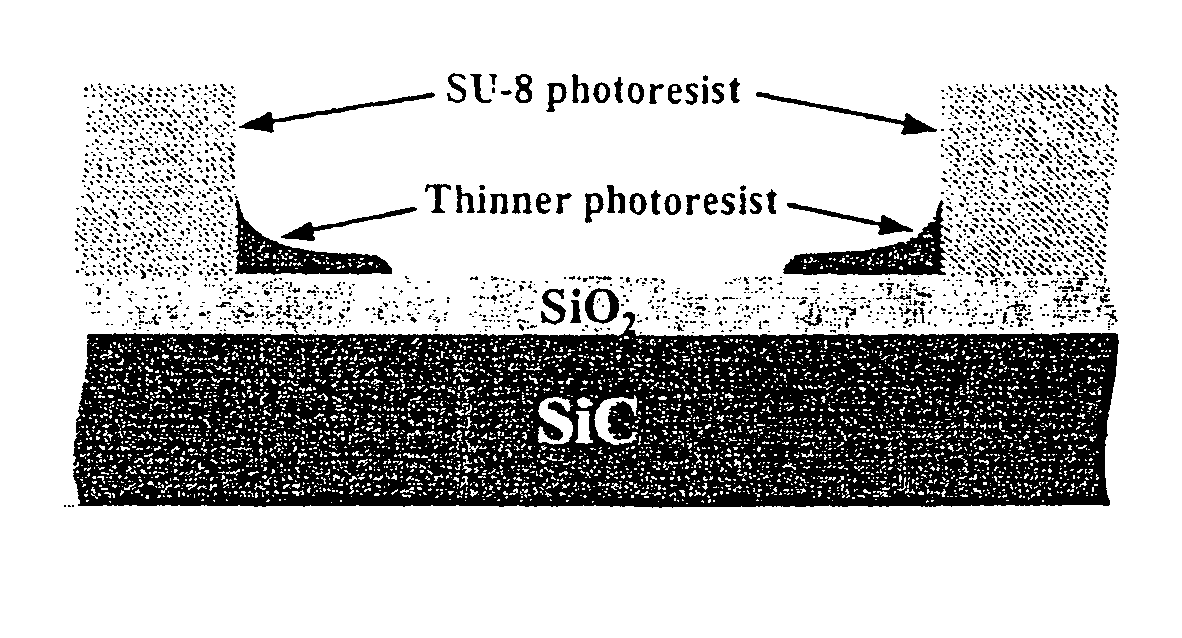
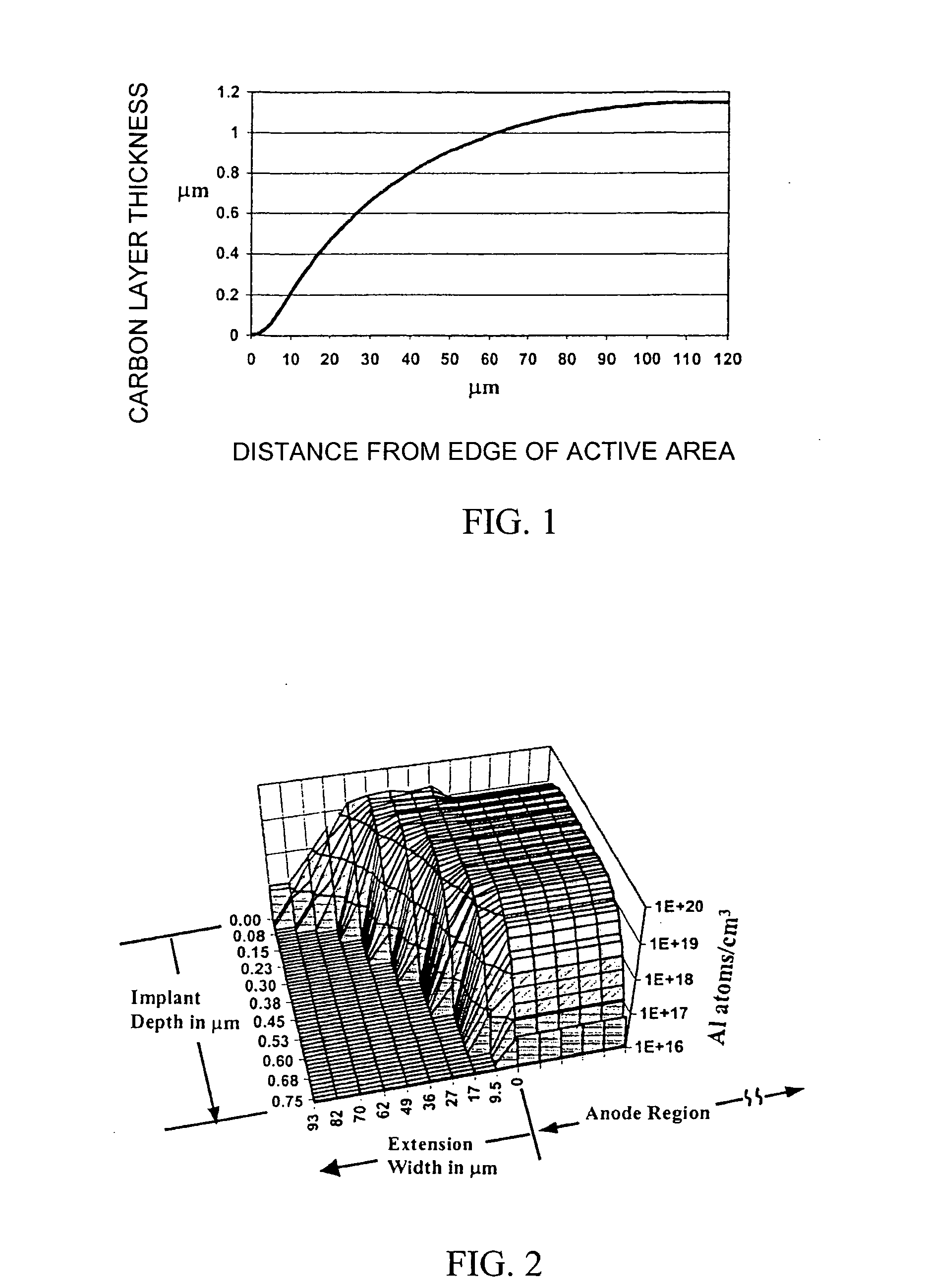
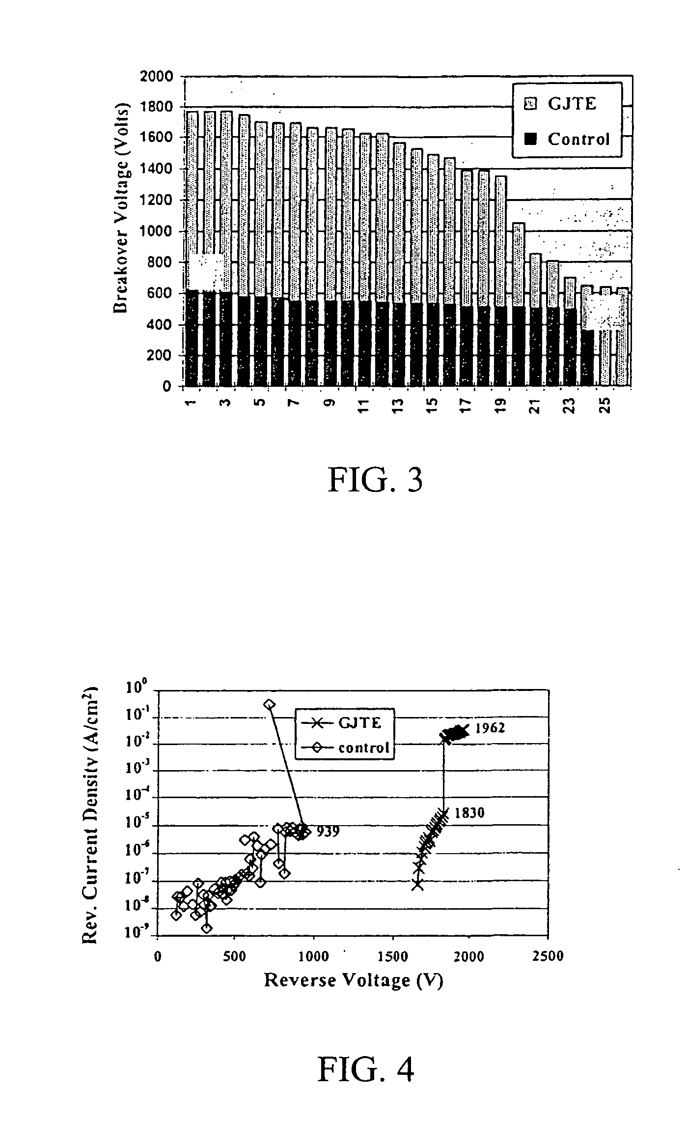
The present invention provides a graded junction termination extension (GJTE) that is self-aligning and can be used to increase the breakdown voltage of silicon carbide junction diodes. The GJTE is made using a graded photoresist mask and a defocused lithography pattern. The key to making a GJTE is the fabrication of a graded photoresist mask that is used to create a carbon implant mask, or as an etch mask for making an oxide implant mask. The GJTE is a very effective, cost-efficient method for power device termination.

Problems solved by technology

In such devices, the maximum reverse voltage that the device can withstand is limited by the breakdown voltage of the reverse-blocking junction.
However, the actual breakdown voltage of the junction normally falls short of the breakdown voltage that might ideally be achieved because of the development of excessively high field strengths at the termination of the junction between the P region and the N region, usually at a location slightly above the metallurgical junction along a region of curvature at the junction termination.
Unfortunately, just as in silicon devices, ideal blocking voltage is difficult to achieve due to effects at the device edge.
This field crowding can cause increased leakage current and ultimately premature breakdown of the device.
Field line crowding can be reduced with etched mesa isolation; however, damage from etching can also cause leakage and premature breakdown at the device edges.
These methods have been successful for the most part, but each method has its particular drawbacks.
Guard rings are often difficult to fabricate; field plates are limited by the strength of the dielectric used; argon implantation can increase reverse leakage current; beveled etching is less effective with abrupt, one-sided negative junctions, and multiple step etching complicates the beveling process with additional fabrication steps.
Junction termination extensions have been widely used, but JTEs are difficult to optimize and implement with a SiC substrate and GJTEs, which require multiple zones of decreasing implant dose in order to achieve ideal breakdown for a junction, are even more difficult to implement.
These difficulties are due in large measure to the fact dopants do not diffuse into the SiC substrate material as they do into silicon, except at extremely high temperatures that tend to destroy the SiC material itself.
More specifically, the combination of implantation / diffusion is not feasible for SiC because almost all atoms have extremely low diffusion coefficients in SiC at temperatures below 2,000° C., which is very nearly the bulk growth temperature of SiC itself.
Thus, traditional masking, implantation, and diffusion techniques typically used to create JTEs and GJTEs in silicon-based semiconductor devices simply are not available for use in SiC-based semiconductor devices.

Method used


Image

  • Graded junction termination extensions for electronic devices
  • Graded junction termination extensions for electronic devices
  • Graded junction termination extensions for electronic devices

Examples


Embodiment Construction

[0020] The following description of the invention is provided as an enabling teaching of the invention in its best, currently known embodiment. Those skilled in the relevant art will recognize that many changes can be made to the embodiment described, while still obtaining the beneficial results of the present invention. It will also be apparent that some of the desired benefits of the present invention can be obtained by selecting some of the features of the present invention without utilizing other features. Accordingly, those who work in the art will recognize that many modifications and adaptations to the present invention are possible and may even be desirable in certain circumstances, and are a part of the present invention. Thus, the following description is provided as illustrative of the principles of the present invention and not in limitation thereof, since the scope of the present invention is defined by the claims.

[0021] Junction termination extension (JTE) is one of s...


PUM

PropertyMeasurementUnit
diameteraaaaaaaaaa
thicknessaaaaaaaaaa
thicknessaaaaaaaaaa

Abstract

A graded junction termination extension in a silicon carbide (SiC) semiconductor device and method of its fabrication using ion implementation techniques is provided for high power devices. The properties of silicon carbide (SiC) make this wide band gap semiconductor a promising material for high power devices. This potential is demonstrated in various devices such as p-n diodes, Schottky diodes, bipolar junction transistors, thyristors, etc. These devices require adequate and affordable termination techniques to reduce leakage current and increase breakdown voltage in order to maximize power handling capabilities. The graded junction termination extension disclosed is effective, self-aligned, and simplifies the implementation process.

Description

CROSS-REFERENCE TO RELATED APPLICATION [0001] Priority to the filing date of U.S. provisional patent application Ser. No. 60 / 342,198 filed on Dec. 19, 2001 is hereby claimed.STATEMENT REGARDING FEDERALLY SPONSORED RESEARCH [0002] The invention disclosed herein was supported by NASA Grant No. NAGV-1192 through the Center for Space Power and Advanced Electronics of the Auburn University Space Power Institute. The U.S. Government has certain rights in the invention.TECHNICAL FIELD [0003] This invention relates generally to power semiconductor devices and more specifically to power semiconductor devices in which graded junction termination extensions (GJT) are formed to increase the breakdown voltage of the device, and to processes for fabricating same. BACKGROUND OF THE INVENTION [0004] Junction termination extensions (JTEs) and graded junction termination extensions (GJTEs) have been utilized as a device edge passivation technique in high voltage simiconductor devices such as MOSFETs,...

Claims


Application Information

Patent Timeline
Patent Type & Authority Applications(United States)
IPC IPC(8): H01L21/302H01L21/04H01L29/06H01L29/24
CPCH01L21/0465H01L29/0615H01L29/1608Y10S438/931
Inventor MERRETT, J. NEILISAACS-SMITH, TAMARASHERIDAN, DAVID C.WILLIAMS, JOHN R.
Owner AUBURN UNIV
Learn More