Power supply, multi chip module, system in package and non-isolated DC-DC converter

a power supply and multi-chip technology, applied in the field of power supply, can solve the problems of increasing on-resistance, increasing conductive loss, and increasing switching loss in comparison with the vertical power mosfet, and achieves the effects of low capacity, low on-resistance, and reducing switching loss and conductive loss

Inactive Publication Date: 2006-08-10
RENESAS TECH CORP
View PDF4 Cites 53 Cited by
  • Summary
  • Abstract
  • Description
  • Claims
  • Application Information

AI Technical Summary

Benefits of technology

[0010] (1) The high side switch is a gallium nitride device with low capacity and low on-resistance. This gallium nitride device is a lateral device. Moreover, this lateral device is a junction field effect transistor using two-dimensional electronic gas. Or, the high side switch is a junction field effect transistor.
[0011] The following is the brief description of the effect obtained by the representatives of the inventions disclosed in this application.
[0012] In accordance with the present invention, it is possible to reduce the switching loss and the conductive loss to enhance the conversion efficiencies and to realize the high efficiency of the power supply by using a gallium nitride device for the high side switch in the non-isolated DC-DC converter.

Problems solved by technology

Now, as the recent power supply is using higher frequency, there has occurred the problem that the switching loss increases especially at the high side switch.
However, with the above mentioned lateral power MOSFET, there is a problem that the on-resistance increases and the conductive loss increases in comparison with the vertical power MOSFET.
As described above, because the trend of the power supply is to use larger current and higher frequency, with the lateral power MOSFET of silicon device with large on-resistance the conductive loss is large and the high efficiency of the system is difficult.

Method used


Image

  • Power supply, multi chip module, system in package and non-isolated DC-DC converter
  • Power supply, multi chip module, system in package and non-isolated DC-DC converter
  • Power supply, multi chip module, system in package and non-isolated DC-DC converter

Examples


embodiment 1

[0036] An example of the power supply according to the embodiment 1 of the present invention will be described using the drawings.

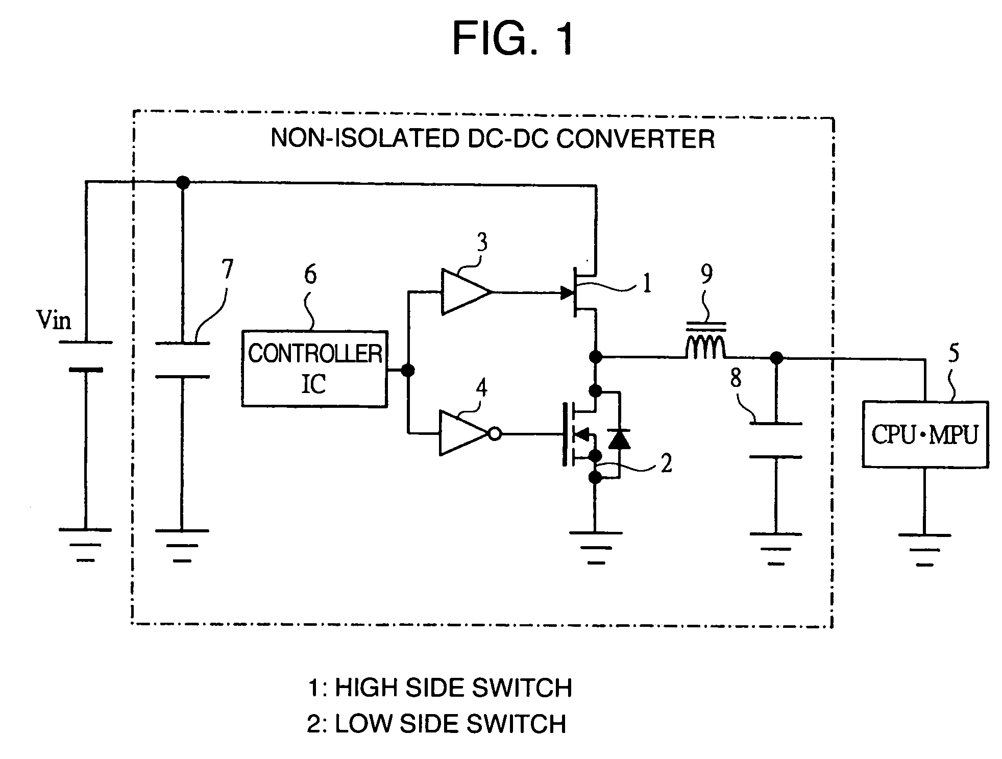
[0037]FIG. 1 shows a circuit diagram of an example of the non-isolated DC-DC converter used in the power supply of this embodiment. The non-isolated DC-DC converter of this embodiment is configured with a high side switch 1 which is a GaN device, a low side switch 2 which is a Si device, a driver IC 3 which drives the high side switch 1, a driver IC 4 which drives the low side switch 2, a controller IC 6 which controls the driver IC 3 and IC 4, an input capacitor 7, an output capacitor 8, and an inductor 9, and a DC power supply Vin is connected to the input side and a CPU / MPU 5 is connected to the output side.

[0038] In this non-isolated DC-DC converter the power is supplied to the CPU / MPU 5 converting the input DC voltage to the desired DC voltage by driving the high side switch 1 and the low side switch 2 by the driver ICs 3, 4, respectively, by the c...

embodiment 2

[0046] An example of the power supply in the embodiment 2 of the present invention will be described using FIGS. 5A and 5B.

[0047]FIGS. 5A and 5B show a chip arrangement diagram (FIG. 5A) and a package plane view (FIG. 5B) of an example of a multi-chip module used in the power supply of this embodiment. The multi-chip module of this embodiment mounts the high side switch 1 and the low side switch 2 which configure the non-isolated DC-DC converter of the above mentioned embodiment 1 on the same package.

[0048] That is, the multi-chip module of this embodiment is, as shown in FIG. 5A, configured with high side chip 36 of high side switch and low side chip 37 of low side switch, and the high side chip 36 is mounted on frame 39, the low side chip 37 is mounted on frame 40, and the high side chip 36 and the frame 40 are connected by wire bonding. Afterward, it is completed as a package after experiencing mold encapsulation and so on. As this package, as shown in FIG. 5B, it results in pa...

embodiment 3

[0051] An example of the power supply in the embodiment 3 of the present invention will be described using FIG. 6.

[0052]FIG. 6 shows a chip arrangement diagram of an example of a system in package used in the power supply of this embodiment. The system in package of this embodiment mounts the high side switch 1, the low side switch 2, and the driver ICs 3, 4 which configure the non-isolated DC-DC converter of the above mentioned embodiment 1 on the same package.

[0053] That is, the system in package of this embodiment is, as shown in FIG. 6, configured with the high side chip 36 of high side switch, the low side chip 37 of low side switch, and driver IC chip 41 of driver IC, and the high side chip 36 is mounted on frame 43, the low side chip 37 is mounted on frame 44, and the driver IC chip 41 is mounted on frame 45. The high side chip 36 and the frame 44, the driver IC chip 41 and the gates of the high side chip 36 and the low side chip 37 are connected by wire bonding respectivel...


PUM


Abstract

A power supply includes a non-isolated DC-DC converter for use in a power source system having a high side switch and a low side switch, in which HEMT or HFET or gallium nitride device with low capacity and low on-resistance is used for the high side switch and a vertical power MOSFET of silicon device with low on-resistance is used for the low side switch.

Description

BACKGROUND OF THE INVENTION [0001] The present invention relates to an IC (Integrated Circuit) for switching used in a power circuit, etc., and in particular, to a technique which is effective applied to the enhancement of the power generation efficiency by a non-isolated DC-DC converter. [0002] Recently, as CPU (Central Processor Unit) and MPU (Micro Processor Unit) used in the personal computer and the server, etc. are using lower voltage and larger current, the use of the larger current and the higher frequency are required in the power supply which supplies power to the CPU and the MPU. [0003] Presently, the non-isolated DC-DC converter used mainly in the above mentioned power supply is configured with a high side switch and a low side switch, and for each of these switches. A vertical power MOS-FET (Metal Oxide Semiconductor-Field Effect Transistor) of silicon device is used respectively. The high side switch is a switch for the control of the DC-DC converter, and the low side ...

Claims


Application Information

Patent Timeline
Patent Type & Authority Applications(United States)
IPC IPC(8): H01L33/00H01L29/22H01L21/338H01L29/778H01L29/78H01L29/812H02M3/155
CPCH01L23/49575H01L25/16H01L2924/13062H01L2924/30107H01L2924/13091H01L2224/49111H01L2224/48247H01L2224/48137H01L2224/48091H01L29/2003H01L29/7787H01L29/7813H01L2924/3011H02M3/1588Y02B70/1466Y02B70/1483H01L2224/0603H01L2924/00014H01L2924/00Y02B70/10
Inventor SHIRAISHI, MASAKI
Owner RENESAS TECH CORP
Why Eureka
Try Eureka