
Ion chromatography system using catalytic gas elimination

Active Publication Date: 2006-08-24
DIONEX CORP
View PDF16 Cites 46 Cited by
  • Summary
  • Abstract
  • Description
  • Claims
  • Application Information

AI Technical Summary

Benefits of technology

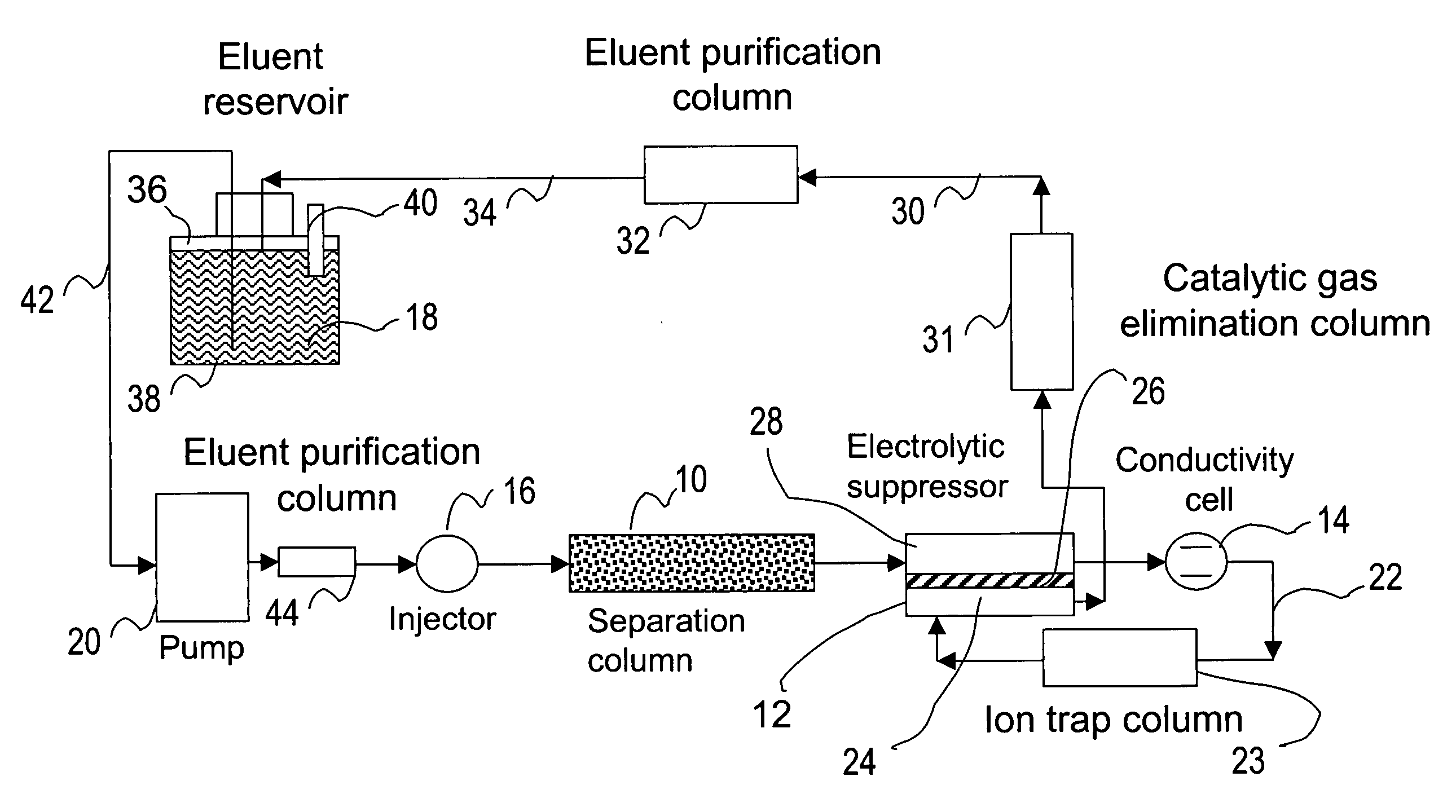
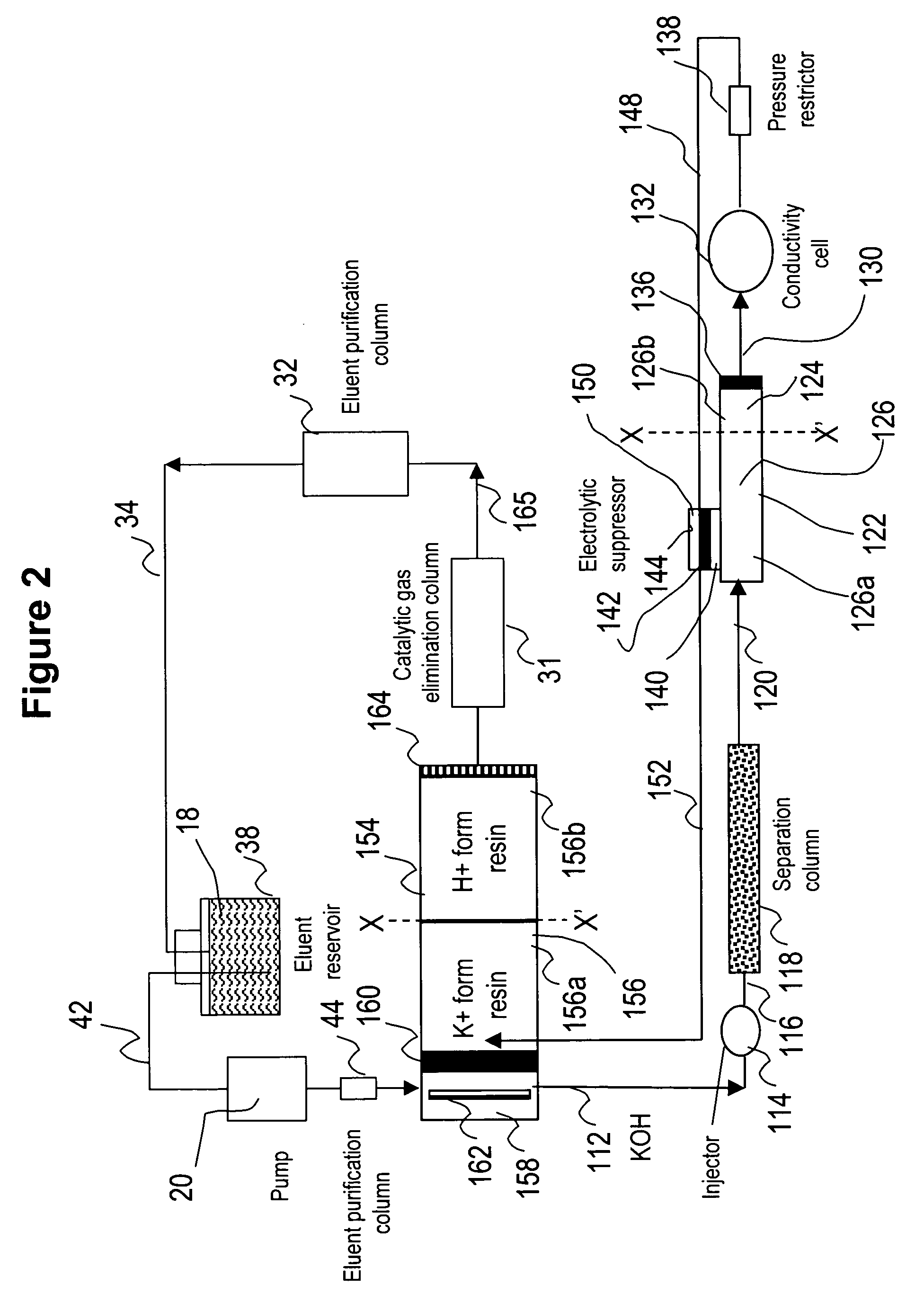
[0009] In one embodiment of the invention, a chromatographic method is provided including the steps of (a) injecting sample ionic species into an aqueous eluent stream, (b) chromatographically separating said sample ionic species in said eluent stream by flowing the same through chromatographic separation medium, (c) detecting said separated sample ionic species in said eluent stream effluent from said chromatographic medium; and (d) catalytically combining hydrogen and oxygen gases, or catalytically decomposing hydrogen peroxide, or both, in said eluent stream in a catalytic gas elimination chamber, to form water and reduce the gas content in said eluent stream.

Problems solved by technology

Off-line preparation of chromatographic eluents can be tedious and prone to operator errors, and often introduces contaminants.
For example, dilute NaOH solutions, widely used as the electrolytes in eluents in the ion chromatographic separation of anions, are easily contaminated by carbonate.
The preparation of carbonate-free NaOH eluents is difficult because carbonate can be introduced as an impurity from the reagents or by adsorption of carbon dioxide from air.
The presence of carbonate in NaOH eluents often compromises the performance of an ion chromatographic method, and can cause an undesirable chromatographic baseline drift during the hydroxide gradient and even irreproducible retention times of target analytes.
The continuous operation of an ion chromatography system can consume a significant amount of eluents.
The consistent preparation of such large amount of the eluent as well as the disposal of the used eluent can pose serious logistical challenges to the system operators in terms of costs and labor, especially in cases where unattended or less frequently attended operations are required.
Even though it overcomes a number of issues associated conventional approaches of eluent preparation in ion chromatography, the use of on-line electrolytic eluent generation devices still requires a constant supply of high purity water from an external source for continuous operation and waste disposal issue remains.

Method used


Image

  • Ion chromatography system using catalytic gas elimination
  • Ion chromatography system using catalytic gas elimination
  • Ion chromatography system using catalytic gas elimination

Examples


example 1

Ion Chromatographic Separation of Common Anions Using an Electrolytic Suppressor and Recycle of a Sodium Carbonate / Sodium Bicarbonate Eluent

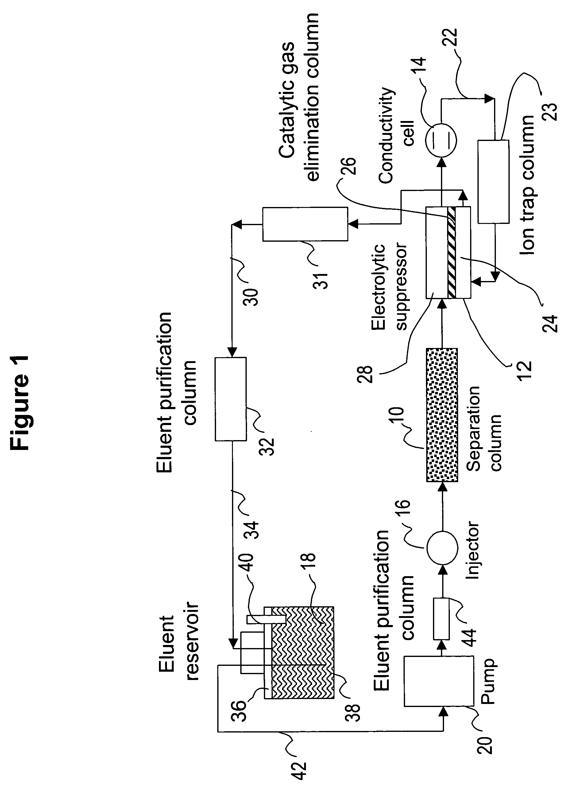
[0083] This example illustrates the use of the eluent-recycle ion chromatography system shown in FIG. 1 for determination of common anions including chloride, nitrate, and sulfate. A Dionex® ICS-1500 ion chromatography system consisting of an isocratic dual-piston high pressure pump, a six-port injector, a column oven, and a conductivity detector was used. A Dionex 4-mm AS4A SC column was used as the separation column, a solution of 3 mM sodium carbonate was used as the eluent, and the separation was performed at 1.5 mL / min. A Dionex anion Atlas® electrolytic suppressor was used in the experiments. The catalytic gas elimination column was prepared by packing small strips of porous Pt foil in a ⅛ OD× 1 / 16 ID×40 cm plastic column. The eluent purification column was packed with ion exchange resins as described previously. In one set of experiments...

example 2

Ion Chromatographic Separation of Common Cations Using an Electrolytic Suppressor and Recycle of a Sulfuric Acid Eluent

[0086] This example illustrates the use of the eluent-recycle ion chromatography system shown in FIG. 1 for determination of common cations including lithium, sodium, ammonium, potassium, magnesium, and calcium. A Dionex DX500 ion chromatography system consisting of a dual-piston high pressure pump, a six-port injector, a column oven, and a conductivity detector was used. A Dionex 4-mm CS12A column was used as the separation column, a solution of 22 mN sulfuric acid was used as the eluent, and the separation was performed at 1.0 mL / min. A Dionex cation Atlas® electrolytic suppressor was used in the experiments. In this example, the catalytic gas elimination column and the eluent purification column were not used. A Dionex TMC-1 trace metal concentrator column was used as the cation trap column placed between the outlet of the conductive cell and inlet of the suppre...

example 3

Ion Chromatographic Separation of Common Cations Using an Electrolytic Suppressor and Recycle of an Eluent Containing Methanesulfonic Acid and 2-Butanone (MEK, Methyl Ethyl Ketone)

[0087] This example also illustrates the use of the eluent-recycle ion chromatography system shown in FIG. 1 for determination of common cations including lithium, sodium, ammonium, potassium, magnesium, and calcium. In this example, a Dionex DX500 ion chromatography system consisting of a dual-piston high pressure pump, a six-port injector, a column oven, and a conductivity detector was used. A Dionex 4-mm CS15 column was used as the separation column, a solution of 12 mM methoanesulfonic acid (MSA) and 5% (v / v) HPLC-grade butanone was used as the eluent, and the separation was performed at 1.0 mL / min. A Dionex cation Atlas® electrolytic suppressor was used in the experiments. No eluent purification or catalytic gas elimination columns were used. A Dionex TMC-1 trace metal concentrator column was used as...


PUM

PropertyMeasurementUnit
Electrical conductivityaaaaaaaaaa
Electric chargeaaaaaaaaaa
Contentaaaaaaaaaa

Abstract

A liquid chromatographic system is provided including catalytically combining hydrogen and oxygen gases in the chromatography eluent stream in a catalytic gas elimination chamber, to form water and thereby reduce the gas content in the eluent stream. Also, a liquid ion chromatographic system in which the effluent from the detector is recycled to a membrane suppressor and then is mixed with a source of eluent for recycle to the chromatographic column.

Description

BACKGROUND OF THE INVENTION [0001] Since it was introduced in 1975, ion chromatography has become a widely used analytical technique for the determination of anionic and cationic analytes in various sample matrices. In ion chromatography, dilute solutions of acids, bases, or salts are commonly used as the electrolytes in chromatographic eluents. Traditionally, [0002] These eluents are prepared off-line by dilution with reagent-grade chemicals. Off-line preparation of chromatographic eluents can be tedious and prone to operator errors, and often introduces contaminants. For example, dilute NaOH solutions, widely used as the electrolytes in eluents in the ion chromatographic separation of anions, are easily contaminated by carbonate. The preparation of carbonate-free NaOH eluents is difficult because carbonate can be introduced as an impurity from the reagents or by adsorption of carbon dioxide from air. The presence of carbonate in NaOH eluents often compromises the performance of an...

Claims


Application Information

Patent Timeline
IPC IPC(8): B01D15/08
CPCG01N30/62G01N30/96G01N2030/965
Inventor LIU, YANPOHL, CHRISTOPHER A.AVDALOVIC, NEBOJSARIVIELLO, JOHN M.SIRIRAKS, ARCHAVA
Owner DIONEX CORP
Learn More