Systems and methods for electrosurgical treatment of fasciitis

a technology of electrosurgical treatment and fasciitis, applied in the field of electrosurgical treatment of fasciitis, can solve the problems of insufficient blood flow to the heart, patients are too sick to successfully undergo bypass surgery, previous endovascular and/or bypass surgery attempts have failed to provide adequate revascularization of the heart muscle, etc., to achieve sufficient rf energy, facilitate healing process, and vascularize the tendon

Inactive Publication Date: 2006-08-24
ARTHROCARE
View PDF76 Cites 151 Cited by
  • Summary
  • Abstract
  • Description
  • Claims
  • Application Information

AI Technical Summary

Benefits of technology

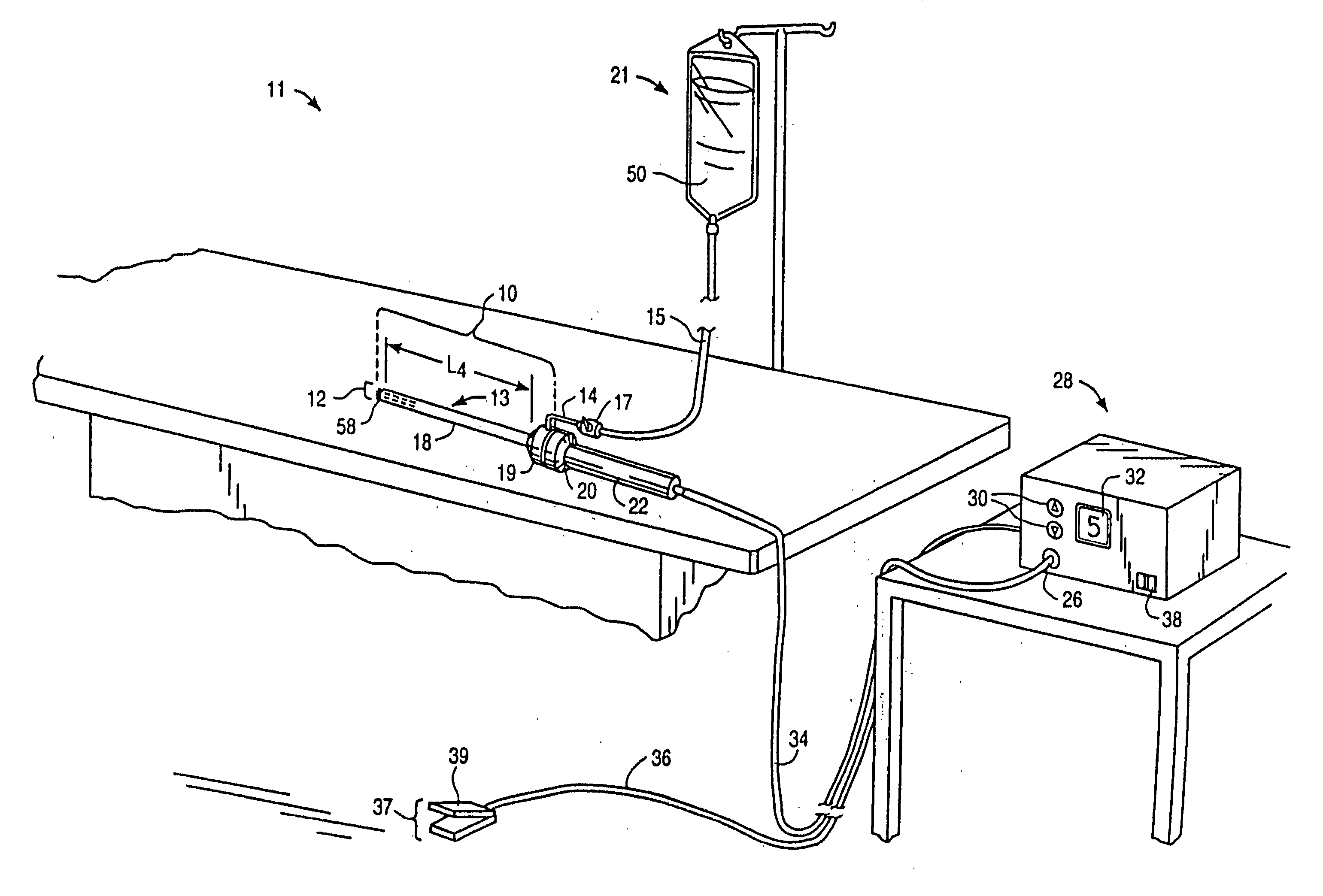
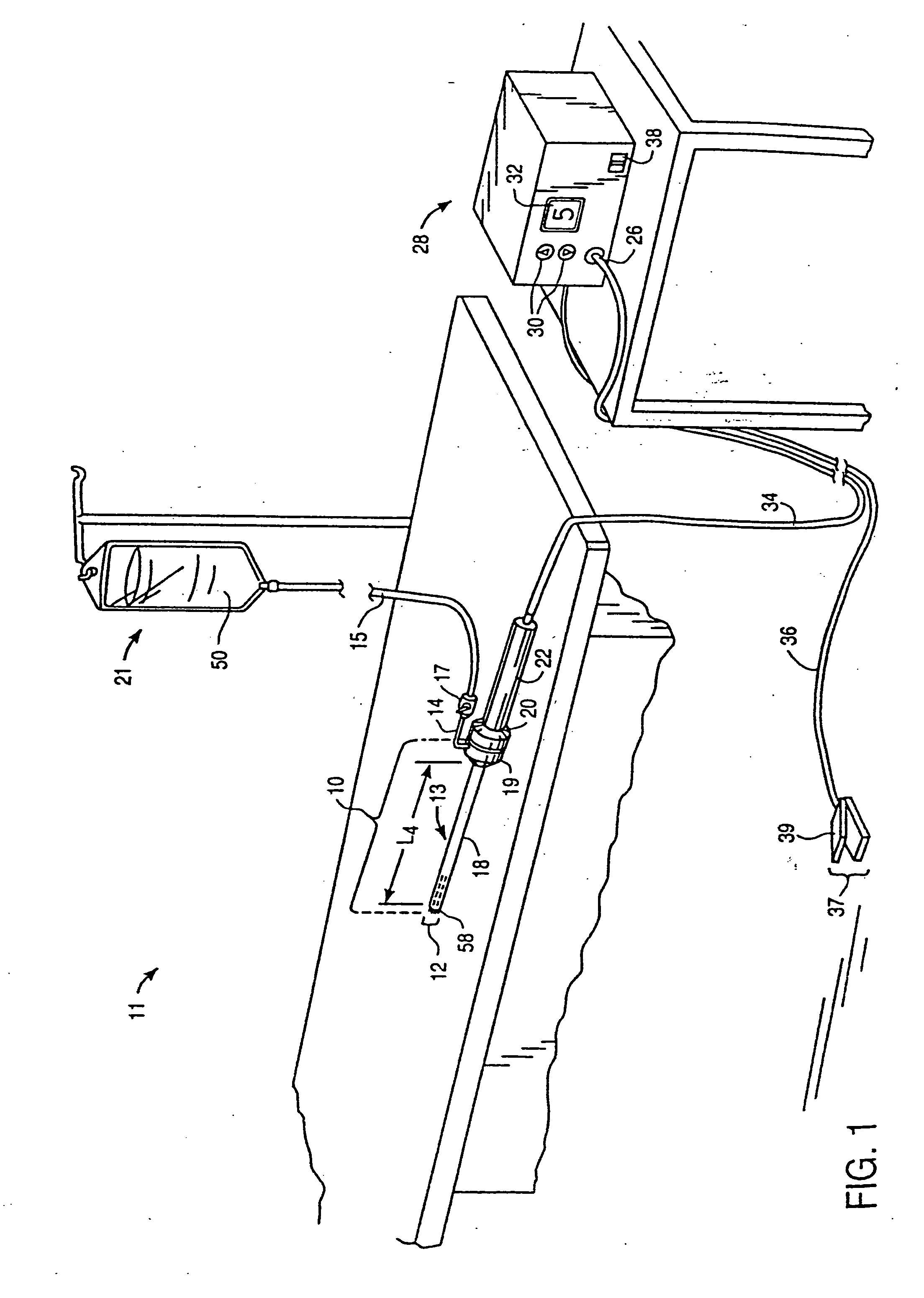
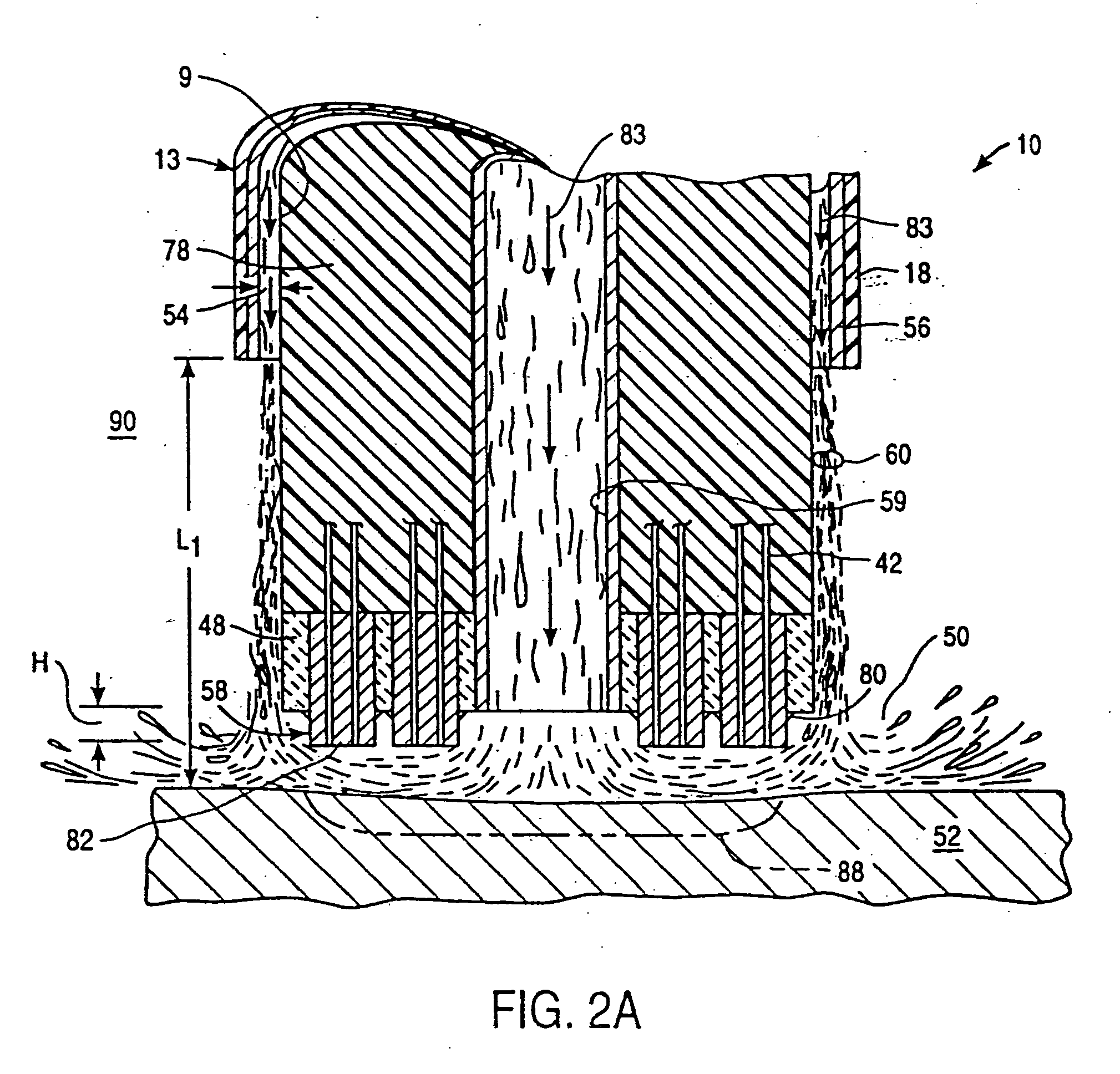
[0017] One of the advantages of the present invention, particularly over previous methods involving lasers, is that the surgeon can more precisely control the location, depth, and diameter of the vascularizing channels formed in the tissue. The ability to precisely control the volumetric removal of tissue results in a field of tissue ablation or removal that is very defined, consistent, and predictable. This precise control of tissue treatment also helps to minimize, or completely eliminate, damage to healthy tissue structures, such as muscles, cartilage, bone, and / or nerves, which may be adjacent to the target tissue. In addition, any severed blood vessels at the target site may be simultaneously cauterized and sealed as the tissue is removed to continuously maintain hemostasis during the procedure. This increases the surgeon's field of view, and expedites the procedure. In one embodiment, the active electrode can remain in contact with the tendon tissue as the high frequency voltage ablates this tissue (or at least substantially close to the tissue, e.g., usually on the order of about 0.1 mm to 2.0 mm, and preferably about 0.1 mm to 1.0 mm). This preserves tactile sense and allows the surgeon to more accurately determine when to terminate cutting of a given channel so as to minimize damage to surrounding tissues and / or to minimize bleeding.
[0018] In open procedures, or in procedures in “dry” fields, the apparatus may further include a fluid delivery element for delivering electrically conductive fluid to the active electrode(s) and the target site. The fluid delivery element may be located on the probe, e.g., in the form of a fluid lumen or tube, or it may be part of a separate instrument. In arthroscopic procedures, however, the surgical area surrounding the tendon will typically be filled with electrically conductive fluid (e.g., isotonic saline) so that the apparatus need not have a fluid delivery element. In both embodiments, the electrically conductive fluid will preferably generate a current flow path between the active electrode(s) and one or more return electrode(s). In an exemplary embodiment, the return electrode is located on the probe and spaced a sufficient distance from the active electrode(s) to substantially avoid or minimize current shorting therebetween and to shield the return electrode from tissue at the target site.

Problems solved by technology

Coronary artery disease, the build up of atherosclerotic plaque on the inner walls of the coronary arteries, causes the narrowing or complete closure of these arteries resulting in insufficient blood flow to the heart.
However, some patients are too sick to successfully undergo bypass surgery.
For other patients, previous endovascular and / or bypass surgery attempts have failed to provide adequate revascularization of the heart muscle.
While recent techniques in LMR have been promising, they also suffer from a number of drawbacks inherent with laser technology.
One such drawback is that the laser energy must be sufficiently concentrated to form channels through the heart tissue, which reduces the diameter of the channels formed by LMR.
Otherwise, the laser beam will damage surrounding portions of the heart as the heart beats and thus moves relative to the laser beam.
Consequently, the surgeon must typically form the channel in less than about 0.08 seconds, which requires a relatively large amount of energy.
Thus, the relatively small diameter channels formed by existing LMR procedures (typically on the order of about 1 mm or less) may begin to close after a brief period of time, which reduces the blood flow to the heart tissue.
Another drawback with current LMR techniques is that it is difficult to precisely control the location and depth of the channels formed by lasers.
For example, the speed in which the revascularizing channels are formed often makes it difficult to determine when a given channel has pierced the opposite side of the heart wall.
In addition, the distance to which the laser beam extends into the heart tissue is difficult to control, which can lead to laser irradiation with heating or vaporization of blood or heart tissue within the ventricular cavity.
As a result, one or more blood thromboses or clots may be formed which can lead to vascular blockages elsewhere in the circulatory system.
Alternatively, when using the LMR technique in an endocardial approach (i.e., from the inside surface of the heart toward the outside surface), the laser beam may not only pierce the entire wall of the heart but may also irradiate and damage tissue surrounding the outer boundary of the heart.
Conditions such as rotator cuff tendinitis, patellar tendinitis, tennis elbow, and plantar fasciitis are extremely common, and yet have no well-defined minimally invasive treatment protocol.
In addition, with age, the meniscus begins to deteriorate, often developing degenerative tears.
Typically, when the meniscus is damaged, the torn pieces begins to move in an abnormal fashion inside the joint.
Because the space between the bones of the joint is very small, as the abnormally mobile piece of meniscal tissue (meniscal fragment) moves, it may become caught between the bones of the joint (femur and tibia).
When this happens, the knee becomes painful, swollen and difficult to move.

Method used


Image

  • Systems and methods for electrosurgical treatment of fasciitis
  • Systems and methods for electrosurgical treatment of fasciitis
  • Systems and methods for electrosurgical treatment of fasciitis

Examples


second embodiment

[0118] In a second embodiment, the detection system can be an ultrasound guidance system that transmits sound waves onto the heart wall to facilitate canalization of the heart.

[0119] Referring to FIGS. 18 and 19, an ultrasound tissue thickness measuring system may be incorporated within an electrosurgical instrument of the invention, e.g., probe 100 or catheter 200, to measure the thickness of the heart wall 260 adjacent to active electrode 270, and thereby allow the surgeon to pre-set the depth of each channel using adjustable stop 352 on handpiece 340 (FIG. 11) before energizing catheter 200 / probe100 and ablating the heart tissue. In the embodiment shown in FIG. 18, an ultrasonic transducer 310, affixed to the distal end of the instrument, and connected to an external ultrasonic generator and sensing system (not shown) via lead 312, transmits pulses of ultrasound into the heart tissue in the form of emitted ultrasound signal 314, and the ultrasound generator and sensing system mea...

third embodiment

[0120] A third embodiment is shown in FIG. 19 wherein an ultrasonic transducer 310 is affixed to the distal end of electrosurgical catheter 200 / probe 100, and connected to an external ultrasonic generator and sensing system (not shown) via leads 312, and transmits pulses of ultrasound into the heart tissue in the form of emitted ultrasound signal 314. The ultrasound generator and sensing system measures the delay time for reflected ultrasound signal 316 to return from the boundary of the heart wall at the surface of epicardium 268 to the sensing system. This measured delay time can be translated into the distance between active electrode 270 and the surface of the epicardium 268. In this arrangement, the surgeon can observe where the channel 264 reaches the preferred distance from the epicardium 268, and can interrupt the application of power and advancement of catheter 200 / probe 100. In one embodiment, the preferred minimum thickness of the uncanalized heart wall 260 (i.e., the min...

fourth embodiment

[0121] A fourth embodiment is shown in FIG. 20, in which an electrosurgical instrument, e.g., probe 100 / 202 includes a small diameter tissue electrical impedance measurement sensor 319 which extends distally from active electrode(s) 270 by a distance L1. Impedance measurement sensor 319 detects the outer surface of the epicardium 268 as sensor 319 enters a region of different electrical impedance (viz, the fluid-filled cavity surrounding the heart). In the present embodiment, a sensor tip 320 may include a first impedance measurement electrode 321 and a second impedance measurement electrode 323. A small, high-frequency potential is applied between first and second impedance measurement electrodes 321 and 323 causing current flow between first and second impedance measurement electrodes 321 and 323 as indicated by current flux lines 322. As the first and second electrodes 321 and 323 emerge from the epicardium 268 into cavity 318 surrounding the heart, the change in electrical imped...


PUM


Abstract

Systems, apparatus, and methods are provided for promoting blood flow to a target tissue. In one aspect, the invention involves canalizing or boring channels, divots, trenches or holes through an avascular connective tissue, or through a tissue having sparse vascularity, such as a tendon or a meniscus, in order to increase blood flow within the tissue. In one method, an active electrode is positioned in close proximity to a target site on a tendon, and a high frequency voltage difference is applied between the active electrode and a return electrode to selectively ablate tendon tissue at the target site, thereby forming a channel or void in the tendon. The active electrode(s) may be moved relative to the tendon during, or after, the application of electrical energy to damage or sculpt a void within the tendon, such as a hole, channel, crater, or the like. In another aspect of the invention, an electrosurgical probe is used to elicit a wound healing response in a target tissue, such as an injured tendon, in order to stimulate vascularization of the target tissue. The present invention may also be used for vascularization of a torn or damaged tissue in conjunction with a surgical repair procedure.

Description

CROSS-REFERENCE TO RELATED APPLICATIONS [0001] This application is a continuation of U.S. patent application Ser. No. 10 / 372,591 filed Feb. 21, 2003, which is a divisional of U.S. patent application Ser. No. 09 / 845,034, now U.S. Pat. No. 6,805,130 which claims priority from U.S. Provisional Application No. 60 / 200,712, filed Apr. 27, 2000, now abandoned, and is a continuation-in-part of U.S. patent application Ser. No. 09 / 089,012, filed Jun. 2, 1998, now U.S. Pat. No. 6,102,046 which is a continuation-in-part of U.S. patent application Ser. No. 08 / 753,227, filed on Nov. 22, 1996, now U.S. Pat. No. 5,873,855, which is a continuation-in-part of U.S. patent application Ser. No. 08 / 562,331, filed on Nov. 22, 1995, now U.S. Pat. No. 5,683,366, the complete disclosures of which are incorporated herein by reference for all purposes. [0002] The present invention is related to commonly assigned co-pending U.S. patent application Ser. No. 08 / 990,374, filed Dec. 15, 1997 (Attorney Docket No. E-...

Claims


Application Information

Patent Timeline
Patent Type & Authority Applications(United States)
IPC IPC(8): A61B18/18A61B17/00A61B18/00A61B18/14A61F2/02A61F2/06A61F2/84A61M1/00
CPCA61B18/148A61B18/1482A61B18/1492A61B2017/00026A61B2017/00106A61B2017/00247A61B2018/0016A61B2018/00178A61B2018/00392A61B2018/00583A61B2018/00702A61B2018/00738A61B2018/00755A61B2018/00875A61B2018/00982A61B2018/1246A61B2018/1253A61B2018/126A61B2018/1273A61B2018/1467A61B2018/1472A61B2018/162A61B2019/5278A61F2/2493A61F2/95A61B2090/3782
Inventor TASTO, JAMES P.WOLOSZKO, JEANEGGERS, PHILIP E.THAPLIYAL, HIRA V.
Owner ARTHROCARE
Why Eureka
Try Eureka