Welded joint made of an austenitic steel

a technology of austenitic steel and welded joints, which is applied in the field of components, can solve the problems of high susceptibility to weld hot cracking, decrease in strength of welds, and difficulty in obtaining high strength, and achieves the effects of reducing high strength, and improving toughness and resistance to hydrogen embrittlemen

Inactive Publication Date: 2006-08-31
NIPPON STEEL CORP
View PDF2 Cites 33 Cited by
  • Summary
  • Abstract
  • Description
  • Claims
  • Application Information

AI Technical Summary

Benefits of technology

[0015] Ti, Al, and Nb easily segregate during solidification, and this leads to a decrease in toughness and resistance to hydrogen embrittlement. However, if Ti and / or Al is added in an amount determined by the amount of Nb, in the later stages of solidification, new nuclei for solidification are formed from the liquid phase and new solid phases develop around the nuclei. As a result, the final solidified portion is divided into small ones. Therefore, the final solidified phase turns into not a large single phase but many finely dispersed phases, and at the time of aging heat treatment, fine Ni3(Al, Ti, Nb) is finely dispersed. Thus, the resulting weld metal has a high strength, and toughness and resistance to hydrogen embrittlement are also improved.
[0016] In a high-Ni alloy which obtains a high strength acheived by the above-described precipitation strengthening, the remains of a continuous liquid phase caused by segregation during solidification, which is the main cause of weld hot cracking, are broken off by dispersion of the final solidified portion, and prevention of weld hot cracking is also achieved.

Problems solved by technology

However, even if it is possible to obtain a high strength base metal, it is difficult to obtain a high strength even with an austenitic weld metal.
Since the weld metal undergoes melting and solidification and the weld heat affected zone undergoes heating and cooling at the time of welding, a decrease in strength occurs in welds.
However, these weld metals have the problem that they have a high susceptibility to weld hot cracking and that it is easy for a decrease in toughness to occur due to hardening caused by precipitation of the above-described intermetallic compounds.

Method used


Image

  • Welded joint made of an austenitic steel
  • Welded joint made of an austenitic steel

Examples


Embodiment Construction

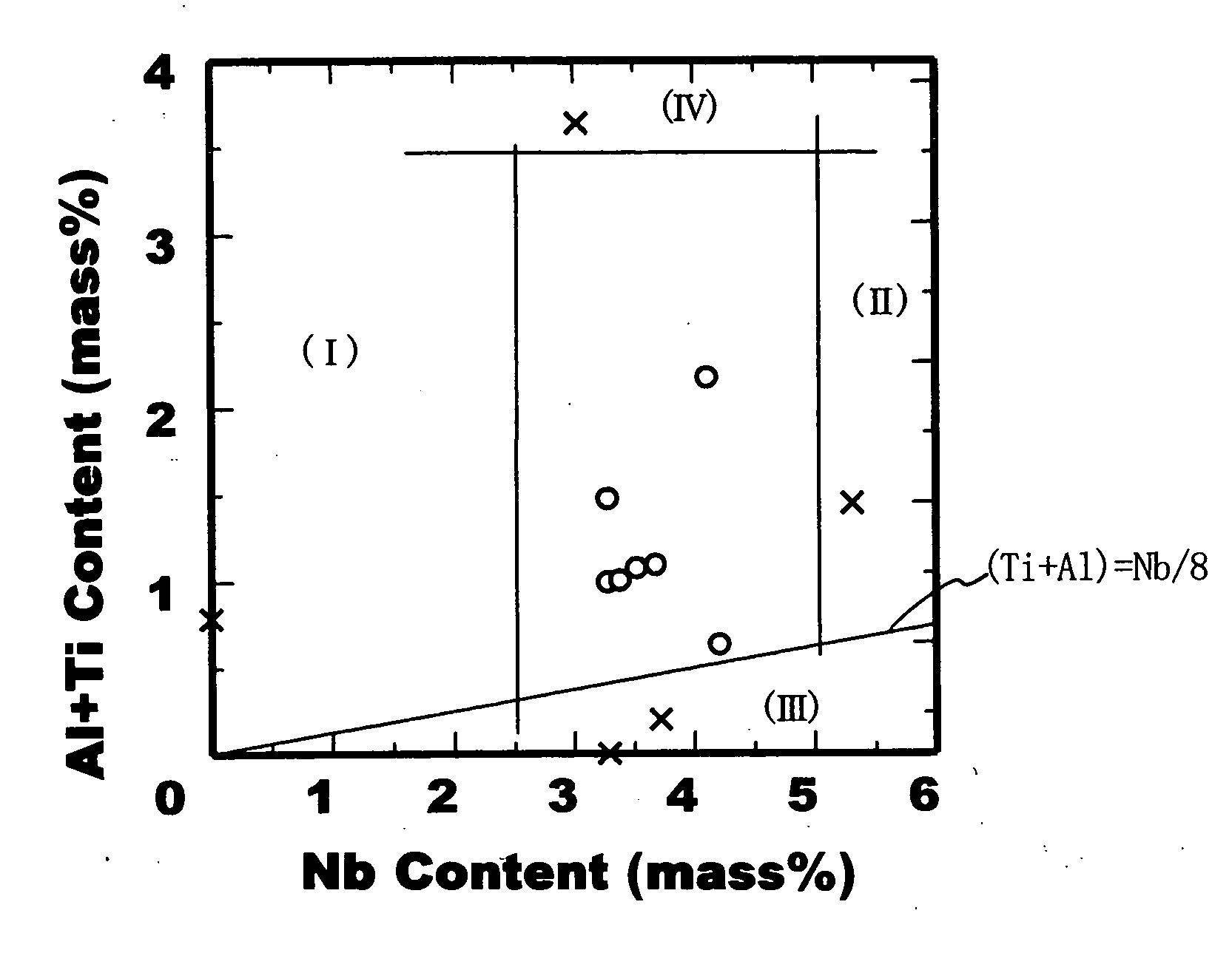
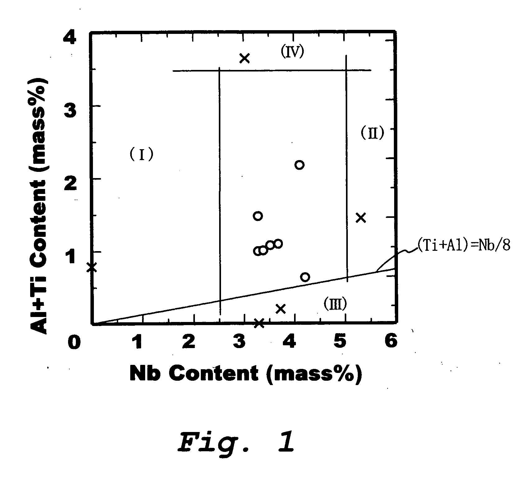
[0071] 50 kg of each of the base metals having the chemical compositions indicated by symbols M1-M4 in Table 1 were melted in a vacuum high frequency furnace, and then they underwent forging to obtain plates with a thickness of 25 mm. They were then subjected to heat treatment by holding for 1 hour at 1000° C. and water cooled to obtain test materials of a weld base metal.

[0072] 50 kg of each of the alloys having the chemical compositions indicated by symbols W1-W5 and Y1-Y5 shown in Table 1 were melted in a vacuum high frequency furnace and worked to form wire with an outer diameter of 2 mm to be used as a welding material.

[0073] In order to evaluate the properties of welds, welded joints were prepared using the above-described weld base metals and welding materials under the below-described conditions, and tests evaluating the properties of the weld metals were carried out.

[0074] A plate measuring 25 mm thick, 100 mm wide, and 200 mm long with a 20° V-shaped bevel in one side o...


PUM

PropertyMeasurementUnit
pressureaaaaaaaaaa
tensile strengthaaaaaaaaaa
temperature toughnessaaaaaaaaaa

Abstract

A weld joint having a base material and a weld metal both of an austenitic steel, wherein the weld metal has a chemical composition, in mass %, that C: 0.04% or less, Si: 1.0% or less, Mn: 3% or less, P: 0.02% or less, S: 0.005% or less, Cr: 15 to 25%, Ni: 30% or more, Mo: 10% or less, Nb: 2.5 to 5%, Al: 3.0% or less, Ti: 0.5% or less, and the balance: Fe and inevitable impurities, the contents of Al and Ti satisfying the following: (Ti+Al)>Nb/8. The weld joint is a high strength austenitic steel weld joint which exhibits excellent toughness at a low temperature and excellent resistance to hydrogen embrittlement, which are required for a piping and a vessel for high pressure hydrogen, particularly also in a welded zone.

Description

TECHNICAL FIELD [0001] This invention relates to a component for use in a hydrogen environment, such as a component made of a high strength austenitic steel having excellent weldability, low temperature toughness, and resistance to hydrogen embrittlement which are properties demanded of piping and the like for use in high pressure hydrogen. More specifically, this invention relates to a welded joint of an austenitic steel having a weld metal with excellent low temperature toughness, resistance to hydrogen embrittlement, and strength. BACKGROUND ART [0002] Today, there is increasing hope for the practical application of fuel cell automobiles. Development of materials is being actively carried out in order to provide materials for use not only in fuel cell automobiles but in high pressure storage vessels, piping, valves, and the like to be used in hydrogen gas stations and the like which are necessary to establish an environment of use for fuel cell automobiles. Such a high pressure e...

Claims


Application Information

Patent Timeline
Patent Type & Authority Applications(United States)
IPC IPC(8): C22C38/58B23K9/173B23K35/02B23K35/30
CPCB23K9/173Y10T428/12958B23K35/3033B23K35/3066B23K2201/06B23K2201/10B23K2201/12B23K2203/04C22C38/001C22C38/02C22C38/44C22C38/48C22C38/50C22C38/58Y10T428/12965Y10T428/12292Y10T428/12972Y10T428/12951B23K35/0261B23K2101/06B23K2101/10B23K2101/12B23K2103/05
Inventor OGAWA, KAZUHIKOIGARASHI, MASAAKISEMBA, HIROYUKIOMURA, TOMOHIKOMIYAHARA, MITSUO
Owner NIPPON STEEL CORP
Why Eureka
Try Eureka