Medical devices with nanoporous layers and topcoats

a technology of nanoporous layers and medical devices, applied in the direction of medical preparations, plant/algae/fungi/lichens ingredients, prosthesis, etc., can solve the problems of porous alumina with porous alumina has severe mechanical integrity problems, and polymer coatings. , to achieve the effect of reducing the risk of delamination

Inactive Publication Date: 2006-08-31
MEDTRONIC VASCULAR INC +1
View PDF51 Cites 158 Cited by
  • Summary
  • Abstract
  • Description
  • Claims
  • Application Information

AI Technical Summary

Problems solved by technology

Polymer coatings, for example, have limitations related to coating adhesion, mechanical properties, inflammatory properties, and material biocompatibility, while porous alumina has severe issues with regard to mechanical integrity.

Method used


Image

  • Medical devices with nanoporous layers and topcoats
  • Medical devices with nanoporous layers and topcoats
  • Medical devices with nanoporous layers and topcoats

Examples


example b

2. EXAMPLE B

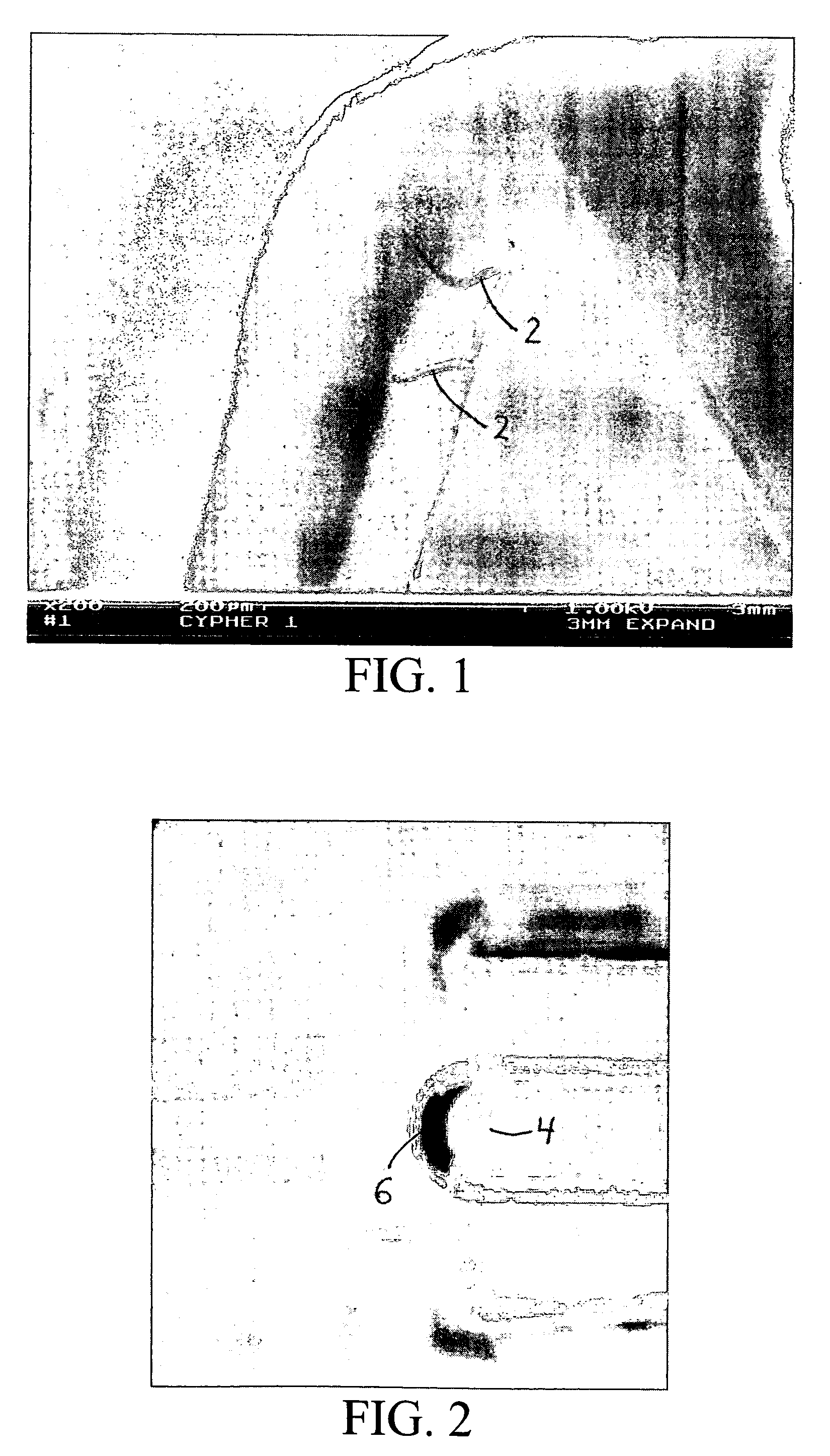
[0205] In another specific example, a coronary stent is co-sputtered with L605 (1.5 A / s) and magnesium (12 A / s) in 2×10⁻³ torr Argon for a resulting alloy coating that is approximately 80% by weight of magnesium. The stent is dealloyed using a 1% HNO3 at about 10 Celsius for about 5 minutes, followed by an anneal at about 600° Celsius for 10 minutes at about 10−5 torr vacuum with a ramp rate of about 200° Celsius / minute. This process produces a dealloyed layer as depicted in the scanning electron micrograph in FIG. 19. The resulting porous zone is approximately 5% by weight of magnesium and has a range of pore sizes from about 10 nm to about 200 nm. In a further embodiment, this stent is loaded with rapamycin using the same procedure as disclosed in Example A, resulting in an initial payload of about 85 micrograms. Place in an in vivo porcine coronary artery stent model results in a 7 day tissue concentration of about 0.80 ng / mg of tissue as measured by tandem MS / MS HPLC...

example c

3. EXAMPLE C

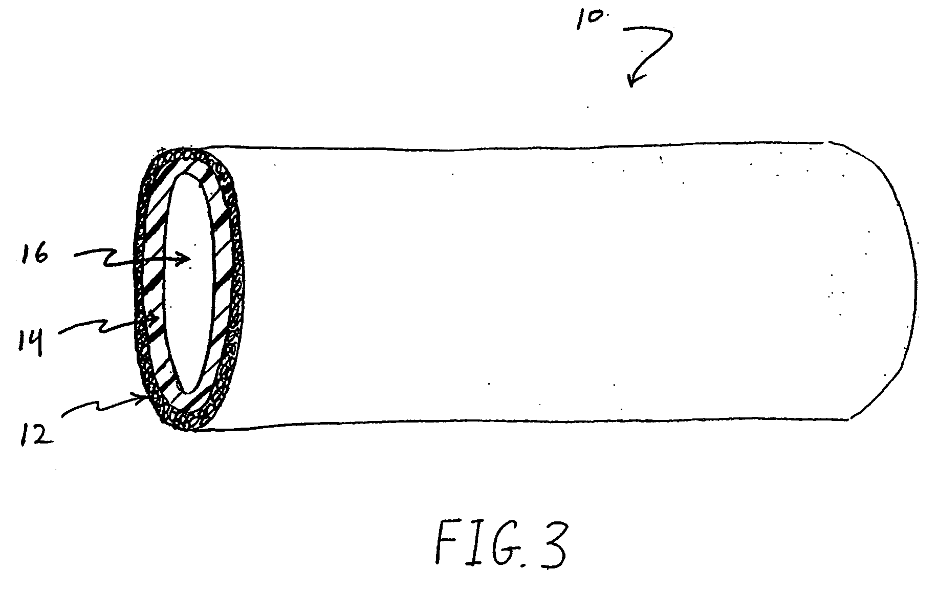
[0206] In still another specific example, a coronary stent undergoes a lower layer sputter deposition with L605 (1.5 A / s) and magnesium (12 A / s) in 2×10⁻³ torr Argon, and followed by an additional upper layer co-sputtering with L605 (3.1 A / s) and Mg (9.7 A / s) in 2×10⁻³ torr Argon, for a resulting alloy coating has a lower layer thickness of about 750 nm and an upper layer with a thickness of about 75 nm. Optionally, one or both sputtering steps may be repeated one or more times, in an alternating or other desired order, to create a layered columnar porous zone. In one embodiment, shown in FIG. 20, an additional two high magnesium content layers, with one lower magnesium content layer is sputtered to produce a five layer porous stent surface. The stent is dealloyed using a 1% HNO3 at about 10 Celsius for about 5 minutes, followed by an anneal at about 600° Celsius for 10 minutes at about 10−5 torr vacuum with a ramp rate of about 200° Celsius / minute. The resulting porous ...

example d

4. EXAMPLE D

[0208] In still example, a coronary stent undergoes a lower layer sputter deposition with L605 (3.1 A / s) and magnesium (9.7 A / s) in 2×10⁻³ torr Argon, for a resulting alloy coating with about 30% magnesium content by weight. The stent undergoes thermal dealloying by heating the porous zone with a heat source at about 600° Celsius for 10 minutes at about 10−5 torr vacuum with a ramp rate of about 200° Celsius / minute. The resulting porous zone is about 10-15% by weight of magnesium with a pore size range of about 1 nm to about 25 nm, but with occasional larger spaces up to about 500 nm or more, as depicted in FIGS. 21A and 21B. Although not wishing to be bound by the theory, it is hypothesized that the different macroscopic morphologies as illustrated in FIGS. 21A and 21B may result from different intrinsic film strains prior to the thermal dealloy process. In one further embodiment, the stent is loaded with rapamycin using an alternative loading procedure as described in ...


PUM

PropertyMeasurementUnit
surface roughnessaaaaaaaaaa
thicknessaaaaaaaaaa
pore sizeaaaaaaaaaa

Abstract

The present invention relates generally to medical devices with therapy eluting components and methods for making same. More specifically, the invention relates to implantable medical devices having at least one porous layer, and methods for making such devices, and loading such devices with therapeutic agents. A mixture or alloy is placed on the surface of a medical device, then one component of the mixture or alloy is generally removed without generally removing the other components of the mixture or alloy. In some embodiments, a porous layer is adapted for bonding non-metallic coating, including drug eluting polymeric coatings. A porous layer may have a random pore structure or an oriented or directional grain porous structure. One embodiment of the invention relates to medical devices, including vascular stents, having at least one porous layer adapted to resist stenosis or cellular proliferation without requiring elution of therapeutic agents. The invention also includes methods, devices, and specifications for loading of drugs and other therapeutic agents into nanoporous coatings.

Description

CROSS-REFERENCE TO RELATED APPLICATIONS [0001] The present application is a continuation of U.S. application Ser. No. 11 / 200,655 filed Aug. 10, 2005, which 1) claims priority under 35 U.S.C. §119(e) to U.S. Provisional Application No. 60 / 602,542 filed on Aug. 18, 2004, U.S. Provisional Application No. 60 / 613,165 filed on Sep. 24, 2004, U.S. Provisional Application No. 60 / 664,376 filed on Mar. 23, 2005, and U.S. Provisional Application Ser. No. 60 / 699,302 filed Jul. 14, 2005, and 2) is a continuation-in-part of U.S. application Ser. No. 10 / 918,853 filed on Aug. 13, 2004, which is a continuation-in-part of U.S. application Ser. No. 10 / 713,244 filed on Nov. 13, 2003, which claims priority under 35 U.S.C. §119(e) to U.S. Provisional Application No. 60 / 426,106 filed on Nov. 13, 2002, the disclosures of which are incorporated by reference herein in their entirety.BACKGROUND OF THE INVENTION [0002] 1. Field of the Invention [0003] The present invention relates generally to medical devices ...

Claims


Application Information

Patent Timeline
Patent Type & Authority Applications(United States)
IPC IPC(8): A61K48/00A61F2/06A61K31/727A61K39/395A61K31/496A61K31/519A61K31/497
CPCA61F2/07A61F2/91A61F2/915A61F2002/91541A61F2250/0067A61L31/022A61F2210/0076A61L31/146A61L31/16A61L31/18A61L2300/606A61L2400/12A61N1/05A61L31/10
Inventor OWENS, GARY K.LYE, WHYE-KEIHUDSON, MATTHEW S.WAMHOFF, BRIAN R.SPRADLIN, JOSHUALOOI, KAREEN
Owner MEDTRONIC VASCULAR INC
Why Eureka
Try Eureka