Water management in bipolar electrochemical cell stacks

a technology of bipolar electrochemical cells and stacks, applied in the direction of cell components, electrochemical generators, cell component details, etc., can solve the problems of limited thickness of flexible organic polymer ion exchange membranes used as solid polymer electrolytes in electrochemical cells, and inability to meet the requirements of electrochemical cell use, etc., to achieve the effect of reducing the number of electrochemical cell stacks and reducing the number of a bipolar electrochemical cell stacks and electrochemical cell stacks of electrochemical cell stacks and electrochemical cell stacks and electrochemical cell stacks and electrochemical cell stacks and electrochemical cell stacks and electrochemical cell stacks and water management and water management, applied in the field of bipolar filter press-type electrochemical cell stacks, which is applied in the field of bipolar filtering and membrane drying effects, which can solve the problem of the electrochemical cell a bipolar electrochemical cell stacks and electrochemical cell stacks of electrochemical cell stacks and electrochemical cell stacks and electrochemical cell stacks and electrochemical cell stacks and electrochemical cell stacks and electrochemical cell

Inactive Publication Date: 2006-09-07
LYNNTECH
View PDF42 Cites 85 Cited by
  • Summary
  • Abstract
  • Description
  • Claims
  • Application Information

AI Technical Summary

Benefits of technology

[0015] During the operation of PEM fuel cells, it is essential that a proper water balance be maintained between a rate at which water is produced at the cathode electrode and rates at which water is removed from the cathode and at which water is supplied to the anode electrode. An operational limit on performance of a fuel cell is defined by an ability of the cell to maintain the water balance as electrical current drawn from the cell into the external load circuit varies and as an operating environment such as the surrounding temperature of the cell varies. For a PEM fuel cell, if insufficient water is returned to the anode electrode, adjacent portions of the PEM electrolyte dry out thereby decreasing the rate at which protons may be transferred through the PEM and also resulting in cross-over of the reducing fuel gas, which is typically hydrogen or a hydrogen rich gas, leading to local over heating. Thus, drying out or localized loss of water, in particular at a reactant inlet, can ultimately result in the development of cracks and / or holes in a proton exchange membrane. These holes allow the mixing of the hydrogen and oxygen reactants, commonly called “cross over,” with a resultant chemical combustion of cross over reactants; loss of electrochemical energy efficiency; and localized heating. Such localized heating can further promote the loss of water from the proton exchange membrane and further drying out of the membrane, which can accelerate reactant cross over. Similarly, if insufficient water is removed from the cathode, the cathode electrode may become flooded effectively limiting oxidant supply to the cathode electrocatalyst and hence decreasing current flow. Additionally, if too much water is removed from the cathode by the oxidant gas stream, the cathode may dry out limiting the ability of protons to pass through the PEM, thus decreasing cell performance.
[0017] In a PEM fuel cell, or in a PEM fuel cell stack, that employs the aforesaid water removal approach, the flow rate of the oxidant gas stream must be sufficiently high to ensure that the oxidant gas stream does not become saturated with water vapor within the flow path across the active area of a cell or cells. Otherwise, saturation of the oxidant gas stream in the flow path across the active area will prevent evaporation of the product and drag water and leave liquid water at the cathode gas diffusion electrode / flow path interface. This liquid water will prevent access of oxidant gas to the active sites of the cathode electrocatalyst thereby causing an increase in cell polarization, i.e., mass transport polarization, and a decrease in fuel cell performance and efficiency. Another disadvantage with the removal of product and drag water by evaporation through the use of an unsaturated oxidant gas stream is that the proton conducting membrane itself may become dry, particularly at the oxidant gas inlet of a cell.
[0022] An electrolyte dry-out barrier to restrict loss of water from the electrolyte in a fuel cell is described in U.S. Pat. No. 6,521,367. The fuel cell has an anode catalyst and a cathode catalyst secured to opposing sides of an electrolyte, porous bipolar plate / flow field assemblies having a water coolant circulating system formed in each of the porous plate assemblies that cause each of the porous plate assemblies to become saturated with water, and an anode electrolyte dry-out barrier secured between the electrolyte and the anode flow field for restricting transfer of water from the electrolyte into the anode flow field. The anode electrolyte dry-out barrier extends from a reducing gas fluid inlet along a reducing gas fluid flow path a distance that is adequate for the reducing gas fluid stream flowing through the anode flow field to become saturated with water. The fuel cell may also include a cathode electrolyte dry-out barrier secured between the electrolyte and the cathode flow field. The anode and cathode electrolyte dry-out barriers may be formed by applying a coating or a film to a porous electrocatalyst support and / or gas diffusion layer, or water transport plate, between the electrolyte and the respective anode or cathode flow field. The coating or film may consist of dry-out barrier materials, compatible with a working environment of a fuel cell, such as a plastic, polymer, elastomer, or resin material with low water absorption properties, a ceramic, or a metal. Additionally, the porous electrocatalyst support or gas diffusion layer may be impregnated with dry-out barrier materials. By providing the fuel cell with anode and cathode electrolyte dry-out barriers, the fuel cell may receive very dry reducing gas and oxidizing gas streams having a zero percent relative humidity without fear of drying out the electrolyte adjacent the reducing gas and oxidizing gas inlets.
[0023] A means of discharging fuel cell product water on the anode side of a PEM fuel cell is described in U.S. Pat. No. 6,576,358. The means comprises a first porous, electron-conducting layer less than 300 μm in thickness disposed on the anode and a second porous, electron-conducting layer less than 300 μm in thickness disposed on the cathode. The second layer on the cathode side is hydrophobic and has a smaller pore size than the first layer on the anode side. The second layer, which can include a support matrix, is formed of an aerogel or a xerogel comprising carbon. The gas-permeable, liquid water impermeable, layer in the form of a carbon aerogel or carbon xerogel / cellulose membrane composite is covered with a smooth skin which has a thickness from about 3 to 4 μm and a pore size≦30 nm. As product water is formed at the cathode electrocatalyst / proton exchange membrane interface it is forced through the proton exchange membrane to the anode where it is removed by means of an excess reducing gas stream from the fuel cell. However, the relatively thick first and second porous layers restrict reactant gas transport to the electrocatalysts / membrane interfaces, especially the transport of air to the cathode electrocatalyst / membrane interface in a system operating at pressures near ambient, and increase the electrical resistance of the fuel cell.
[0027] However, there is still a need for an improved electrochemical cell structure or design, where the electrochemical cell is either a fuel cell or an electrochemical hydrogen concentrator supplied with hydrogen gas or a hydrogen-containing gas as a reductant, that is suitable for satisfying in a passive manner, under a broad range of cell operating conditions one or more of the following requirements: (i) avoidance of drying out at the anode electrocatalyst / proton exchange membrane interface; (ii) avoidance of flooding at the cathode electrocatalyst / proton exchange membrane interface; (iii) maximizing the recovery of liquid water from the anode compartment of the electrochemical cell; and (iv) minimizing the evaporation of water from the cathode compartment. It would be desirable if the fuel cell or electrochemical hydrogen concentrator did not rely on external humidification of reactant gases or high reactant gas flow rates. It would be even more desirable to have an electrochemical cell structure or design that did not dry out under operating conditions of elevated temperature at atmospheric pressure or subatmospheric pressure at ambient temperatures and did not require active water management or active liquid water recovery systems.

Problems solved by technology

In general, thin, flexible organic polymer ion exchange membranes used as solid polymer electrolytes in electrochemical cells are limited to operating temperatures of less than 100° C. at pressures close to atmospheric pressure since ion conduction through these membranes requires that the membranes be at least partially saturated with water in the liquid phase.
Furthermore, membrane drying effects arising from this mechanism will tend to be non-uniform in the plane of the membrane and will be more pronounced at the points of introduction of the reactant gas(es) into the electrochemical cell.
While the PEM, or at least the anode electrocatalyst / membrane interface, is subject to drying the cathode electrocatalyst / membrane interface can be the subject of flooding.
For a PEM fuel cell, if insufficient water is returned to the anode electrode, adjacent portions of the PEM electrolyte dry out thereby decreasing the rate at which protons may be transferred through the PEM and also resulting in cross-over of the reducing fuel gas, which is typically hydrogen or a hydrogen rich gas, leading to local over heating.
Thus, drying out or localized loss of water, in particular at a reactant inlet, can ultimately result in the development of cracks and / or holes in a proton exchange membrane.
These holes allow the mixing of the hydrogen and oxygen reactants, commonly called “cross over,” with a resultant chemical combustion of cross over reactants; loss of electrochemical energy efficiency; and localized heating.
Similarly, if insufficient water is removed from the cathode, the cathode electrode may become flooded effectively limiting oxidant supply to the cathode electrocatalyst and hence decreasing current flow.
Additionally, if too much water is removed from the cathode by the oxidant gas stream, the cathode may dry out limiting the ability of protons to pass through the PEM, thus decreasing cell performance.
This approach has a disadvantage in that it requires that the incoming oxidant gas be almost unsaturated so that the product water (and any water dragged from the anode to the cathode) will evaporate into the unsaturated oxidant gas stream.
This liquid water will prevent access of oxidant gas to the active sites of the cathode electrocatalyst thereby causing an increase in cell polarization, i.e., mass transport polarization, and a decrease in fuel cell performance and efficiency.
Another disadvantage with the removal of product and drag water by evaporation through the use of an unsaturated oxidant gas stream is that the proton conducting membrane itself may become dry, particularly at the oxidant gas inlet of a cell.
Where air is the oxidant gas stream, these high flow rates require a large air circulation system and may cause a decrease in the utilization of the oxidant, i.e., in the fraction of reactant (oxygen) electrochemically reduced to form water.
A decrease in the utilization of the oxidant gas lowers the overall efficiency of the fuel cell and requires a larger capacity pump and / or blower to move the oxidant gas stream through the flow field in order to entrain the product water.
However, this technique has its drawbacks.
For example, high reactant gas flow rates may require a significant consumption of energy, thereby reducing the overall efficiency of the fuel cell system.
Still further, the complexity or efficiency of some fuel cell designs has not been optimized.
However, due to the constraints placed on water transport plates, such as pore size, resistivity, particle size, resin content and yield strength, these plates are costly to manufacture and possess limited strength.
However, the relatively thick first and second porous layers restrict reactant gas transport to the electrocatalysts / membrane interfaces, especially the transport of air to the cathode electrocatalyst / membrane interface in a system operating at pressures near ambient, and increase the electrical resistance of the fuel cell.

Method used


Image

  • Water management in bipolar electrochemical cell stacks
  • Water management in bipolar electrochemical cell stacks
  • Water management in bipolar electrochemical cell stacks

Examples


Embodiment Construction

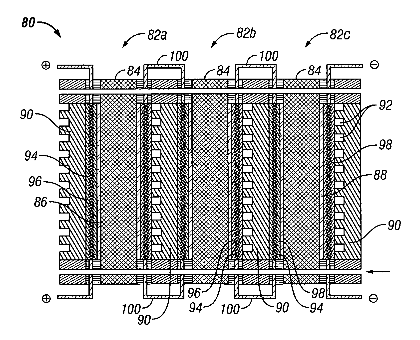
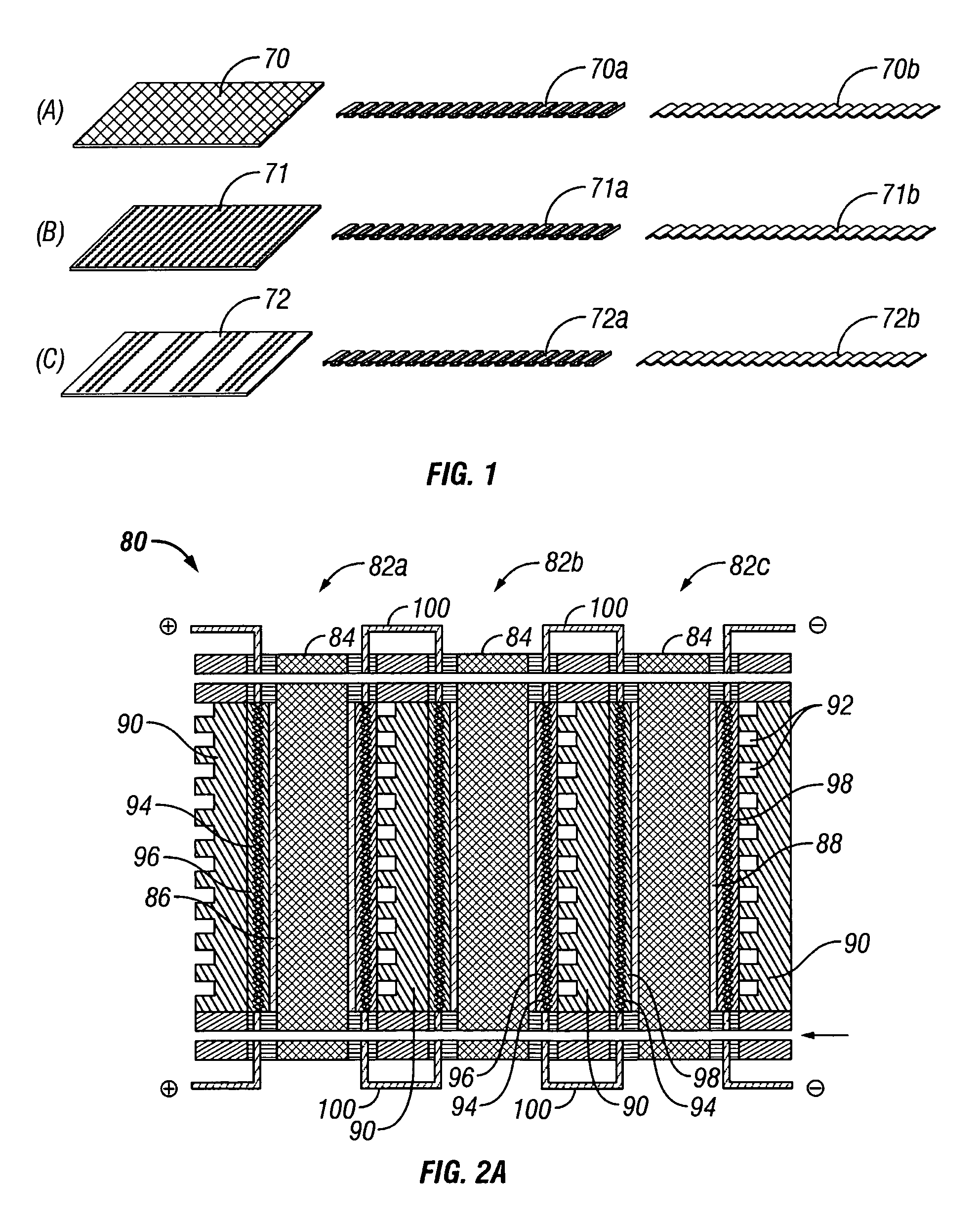
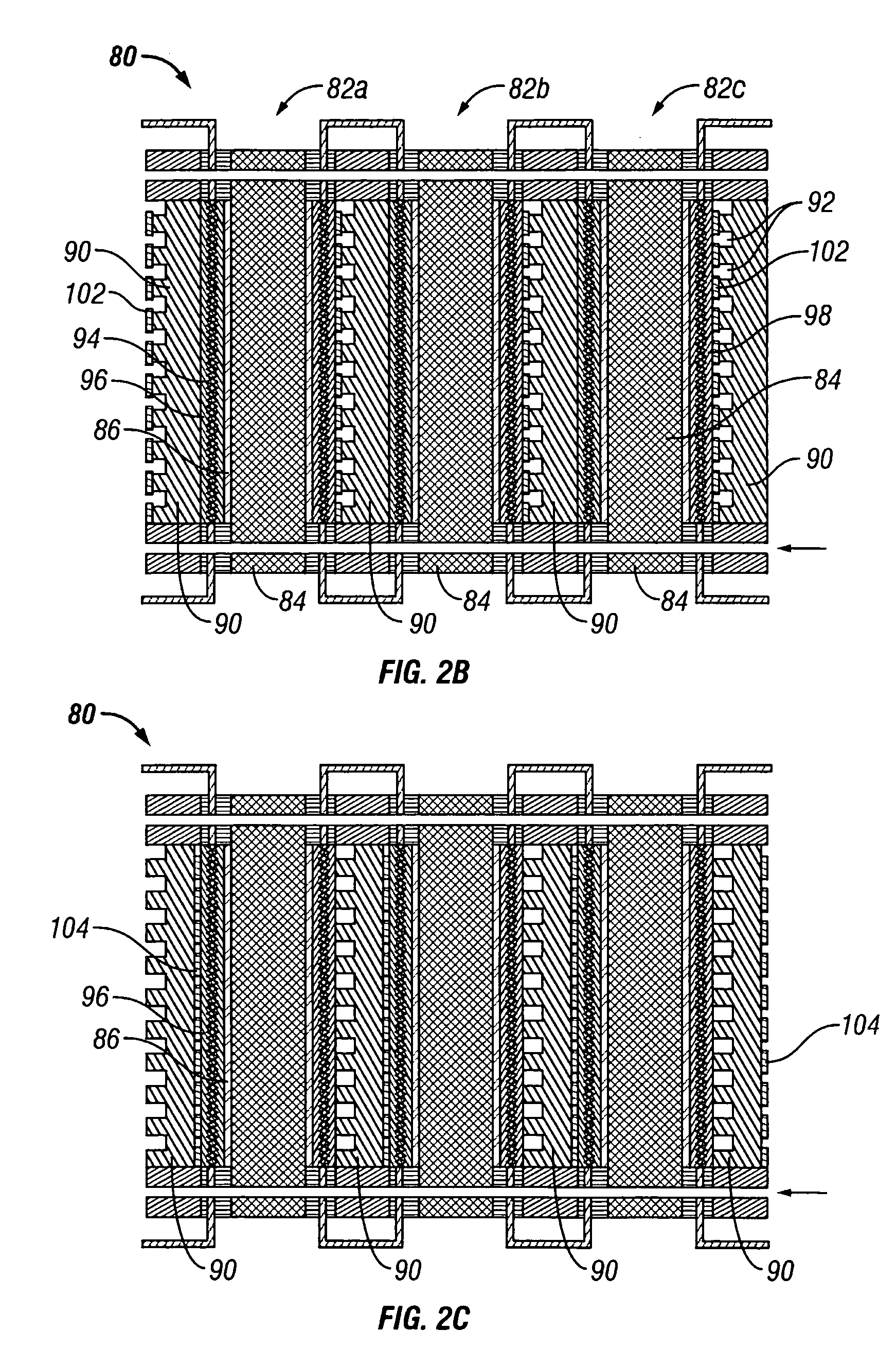
[0041] The present invention provides an electrochemical cell (or an electrochemical cell stack) supplied with a gaseous anodic reactant and either supplied with a gaseous cathodic reactant or producing a gaseous cathodic product. The cell avoids drying out at the anode electrocatalyst / ion exchange membrane interface, avoids flooding at the cathode electrocatalyst / ion exchange membrane interface, facilitates recovery of liquid water from the electrochemical cell at the anode compartment, and at the same time hinders the vaporization of water from the cathode. The electrochemical cell of the present invention is either a fuel cell or an electrochemical hydrogen gas concentrator where the fuel cell or the concentrator is supplied with a source of hydrogen gas as a reactant at the anode. In the case of the fuel cell, the gaseous oxidant is oxygen gas (or air), chlorine gas, or bromine gas. In the electrochemical hydrogen concentrator, the cathodic product is hydrogen gas. In the fuel c...


PUM

PropertyMeasurementUnit
thicknessaaaaaaaaaa
thicknessaaaaaaaaaa
pore sizeaaaaaaaaaa

Abstract

A bipolar, filter press-like electrochemical cell stack comprising a plurality of electrochemical cells, where each electrochemical cell is supplied with a gaseous anodic reactant and either supplied with a gaseous cathodic reactant or produces a gaseous cathodic product, and where each electrochemical cell avoids drying out the ion exchange membrane polymer electrolyte, avoids flooding at the cathode, facilitates recovery of liquid water at the anode, and reduces water losses from at least one of the electrodes. A water retention barrier is variously positioned, such as between a gas diffusion electrode and a fluid flow field. The barrier may be either: (i) a thin, gas permeable, liquid water impermeable membrane; (ii) a thin, porous sheet of material; or (iii) a thin, substantially solid sheet of material except for a plurality of small through-holes that penetrate from one side of the sheet to an opposing side of the same sheet. The barrier is advantageously used at the cathode and facilitates air cooling of the cell.

Description

[0001] This application claims priority to U.S. Provisional Patent Application Ser. No. 60 / 657,820, filed on Mar. 2, 2005.BACKGROUND OF THE INVENTION [0002] 1. Field of the Invention [0003] The present invention relates to bipolar filter press-like electrochemical cell stacks supplied with gaseous reactants, preferably with an oxidizing gas (oxidant) and a reducing gas (reductant) and the operation of such electrochemical cell stacks. [0004] 2. Background of the Related Art [0005] Fuel cells are a type of electrochemical cell that produces electrical energy as a result of electrochemically combining chemical reactants, commonly referred to as a fuel and an oxidant, within the fuel cells and producing at least one chemical product as well as releasing thermal energy. In a fuel cell, electrical energy is produced due to electrochemical oxidation reactions and electrochemical reduction reactions taking place within the fuel cell. A fuel cell can use hydrogen gas as a fuel (or reductant...

Claims


Application Information

Patent Timeline
Patent Type & Authority Applications(United States)
IPC IPC(8): H01M8/24H01M8/10H01M4/94H01M8/04
CPCH01M4/8605H01M8/023H01M8/0232H01M8/0239H01M8/0245H01M8/04291H01M8/2405H01M2008/1095Y02E60/50H01M8/2457H01M8/2465
Inventor FIEBIG, BRADLEY N.CISAR, ALAN J.MURPHY, OLIVER J.HOUY, DANIEL F.WILLIAMS, NICOLE L.
Owner LYNNTECH
Why Eureka
Try Eureka