Wavelength division multiplex optical regeneration system and wavelength division multiplex optical regeneration method

a regeneration system and wavelength division technology, applied in multiplex communication, instruments, optical elements, etc., can solve the problems of large power consumption in the optical signal regenerating system, deterioration of the waveform of the optical signal, timing and intensity,

Inactive Publication Date: 2006-09-14
FURUKAWA ELECTRIC CO LTD
View PDF7 Cites 33 Cited by
  • Summary
  • Abstract
  • Description
  • Claims
  • Application Information

AI Technical Summary

Benefits of technology

[0088] Yet another embodiment of a Kerr-shutter in accordance with the present invention is a Kerr-shutter wherein the

Problems solved by technology

It is inevitable for an optical signal to deteriorate in its waveform, timing and intensity when it travels a long distance.
There has been a difficulty in downsizing and a disadvantage of large power consumption in the optical signal regenerating system which includes so many units.
Furthermore, when the optical signal regenerating system is used in a metro network system and an access network system, it is necessary to install 320 channel optical signal regenerating systems at many relay points, and consequently the whole optical communication system becomes bigger and the cost and the power consumption increase.
However, the regenerator used in the optical signal regenerating system is made of an electric device to process the electric signals so it has a physical upper limitation in the response speed.
Therefore, the regenerating system using an electric device has a limitation in the transmission speed of each channel and it is difficult to realize a downsizing and reduce the power consumption in the real application.
However, this whole optical signal regenerator uses an electric modulator, so that there is an upper limitation in the processing speed similarly to the optic

Method used


Image

  • Wavelength division multiplex optical regeneration system and wavelength division multiplex optical regeneration method
  • Wavelength division multiplex optical regeneration system and wavelength division multiplex optical regeneration method
  • Wavelength division multiplex optical regeneration system and wavelength division multiplex optical regeneration method

Examples


first embodiment

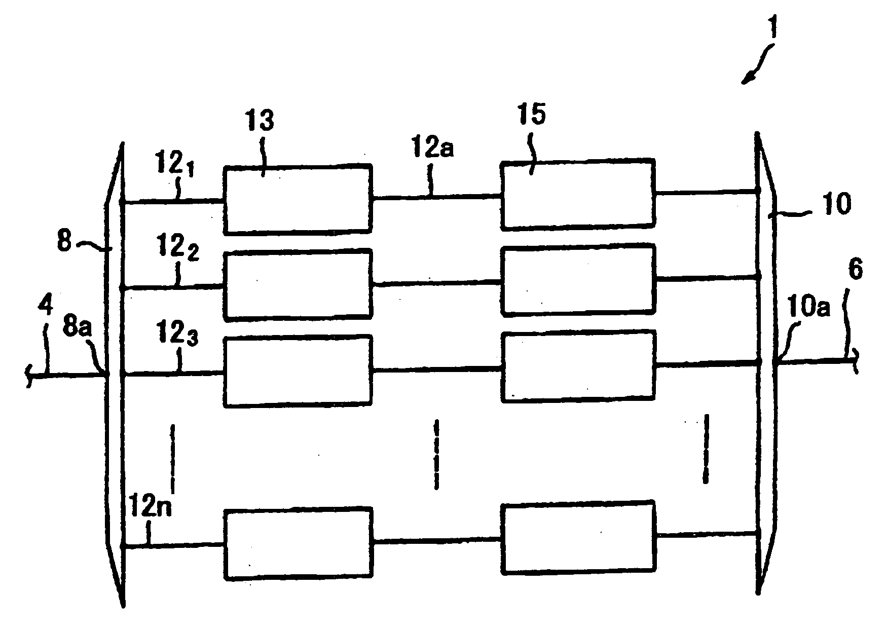
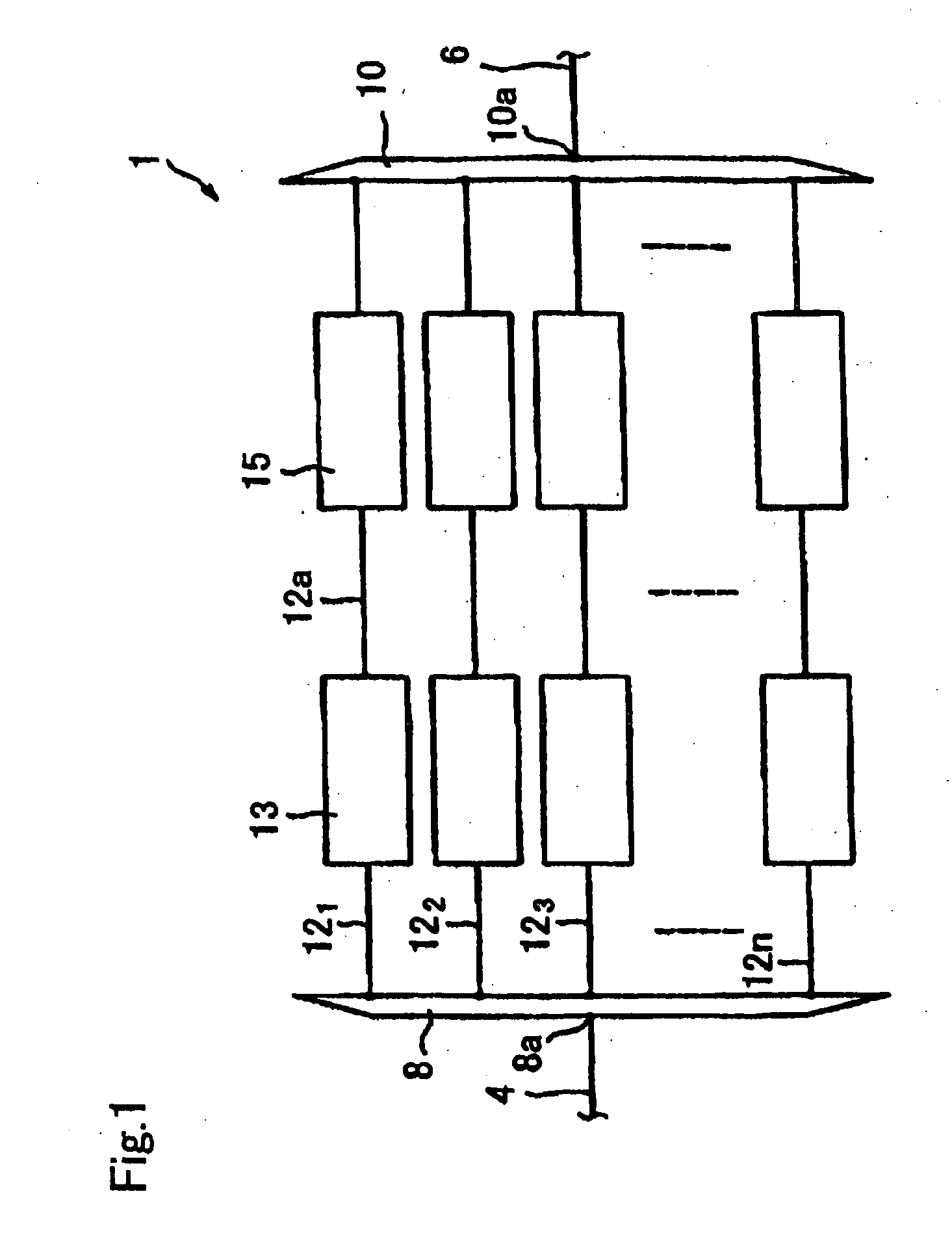
[0214]FIG. 1 shows first embodiment of the wavelength division multiplexing optical regeneration system 1 in accordance with the present invention (hereinafter called “regenerating system 1”).

[0215] The regenerating system 1 is used in the configuration installed in the wavelength division multiplexing optical communication system, for example it is inserted between the optical fiber 4 and the optical fiber 6.

[0216] The regenerating system 1 recovers and regenerates a degenerated signal included in a wavelength division multiplexing light, where the degeneration is caused when a wavelength division multiplexing light transmits in the path in the wavelength division multiplexing optical communication system, to the conditions before transmission such as conditions just after emitted from the signal generator. The degeneration means that at least one selected from a group consisting of a level of intensity, a phase, a frequency or a polarization condition or combination thereof, chan...

second embodiment

[0290]FIG. 13 shows the wavelength division multiplexing optical regeneration system 103 (hereinafter, called a regenerating system 103) in accordance with the present invention.

[0291] The regenerating system 103 is the identical configuration to the regenerating system 1 except that: an optical amplifier 105 is inserted in the optical paths 121, 122, 123, . . . 12n, extending from the demultiplexer 8 to the polarizing converter 13; and a variable dispersion compensator 107 is inserted in the polarization maintaining waveguide 12a, 12b, 12c . . . 12n extending from the polarizing converter 13 to the optical signal regenerating system 1 (refer to FIG. 1).

[0292] The optical amplifier 105 is placed between the demultiplexer 8 and the polarizing converter 13 and receives the optical signals λ1, λ2, λ3, λn transmitted in the optical paths 121, 122, 123, . . . 12n from the demultiplexer 8. The optical amplifier 105 amplifies the optical signals λ1, λ2, λ3, . . . λn to be at predetermined...

third embodiment

[0298]FIG. 14 is a schematic view of the wavelength division multiplexing optical regeneration system 109 (hereinafter, called a regenerating system 109) in accordance with the present invention.

[0299] The regenerating system 109 is the identical configuration to the regenerating system 103 shown in FIG. 13 except that the polarization mode dispersion compensator 110 is inserted in the polarization maintaining waveguide 12a, 12b, 12c . . . 12n extending from the variable dispersion compensator 107 to the regenerating system 15.

[0300] This polarization mode dispersion compensator 110 is a device to compensate the polarization mode dispersion which is a phenomenon that the birefringency existing randomly and locally in the transmitting path makes the difference in the transition speed among polarization mode to make a distortion in the time waveform of the optical signal.

[0301] Consequently, by this regenerating system 109, a distortion of the waveform by the polarization mode dispe...


PUM


Abstract

An optical regeneration system for regenerating a degenerated signal light, comprising a regeneration device having at least one of a soliton converter, a pulse roller, a Kerr-shutter and a soliton purifier. The solilton converter uses an anomalaous-dispersion fiber (ADF) having a fiber length up to three times the soliton frequency, and the pulse roller is provided with a pulse roller fiber having high non-linear characteristics. The Kerr-shutter comprises an optical LO (local oscillation) generator for generating an optical LO on an OPLL (optical phase locked loop), a phase comparator for detecting the phase difference between an externally-input signal light and an optical LO, and a control unit for regulating the repeated frequency of an optical LO based on the phase difference. The soliton purifier has a soliton fiber disposed between two optical fibers.

Description

TECHNICAL FIELD [0001] The present invention relates to a wavelength division multiplex optical regeneration system and a wavelength division multiplex optical regeneration method. BACKGROUND ART [0002] There is continuously increasing a transmission capacity of the communication systems, and the capacity has been significantly increasing due to a progress of an optical fiber used in a communication system. For example, the communication systems are categorized into a point-to-point trunk line network system, a metro network system and an access network system, the optical communication system has already been deployed in the trunk line network system, in addition, even in the metro network system and the access network system, an electrical communication system is going to be replaced with the optical communication system. Namely, the whole communication system is progressing to adopt the optical communication system. [0003] Recently, the information capacity transmitted via one op...

Claims


Application Information

Patent Timeline
IPC IPC(8): G02B6/28H04B10/00G02F1/35G02F1/365H01S3/10H04B10/2507H04B10/2537H04B10/299H04B10/40H04B10/50H04B10/60H04J14/00H04J14/02
CPCG02F1/3513H04B10/25077H04B10/299
Inventor IGARASHI, KOJIMATSUSHITA, SHUNICHINAMIKI, SHUTAKASAKA, SHIGERHIROINOUE, TAKASHITOBIOKA, HIDEAKIHIROISHI, JIRO
Owner FURUKAWA ELECTRIC CO LTD
Why Eureka
Try Eureka