Polarization plate protection film

Inactive Publication Date: 2006-09-21
ZEON CORP
View PDF3 Cites 12 Cited by
  • Summary
  • Abstract
  • Description
  • Claims
  • Application Information

AI Technical Summary

Benefits of technology

[0014] As the result of intensive studies by the present inventors to develop the protective film for polarizing plates exhibiting the excellent functions described above, it was found that a film which comprised a thermoplastic film having a photoelastic coefficient and a saturated water absorption in respective specific ranges and an antireflection layer formed at least on one face of the th

Problems solved by technology

When a display device such as the liquid crystal display device is used, light from the outside is occasionally reflected at the surface of the display, and difficulty arises in watching images on the display.
However, it was found by the studies by the present inventors that, when a polarizing plate was prepared by using a conventional protective film for polarizing plates and mounted to a liquid crystal display device, problems arose in that the distribution of luminance and the distribution of color difference became uneven, and images showed fluctuation, flicker and uneven color.
As the result, the thickness of the antireflection layer became uneven within the surface of the film, and the reflectance fluctuated.
It was found that microscopic damages were formed on the surface of the film during the repeated winding and unwinding, and wrinkles were formed in the film due to the change in the temperature during the repeated winding and unwinding.

Method used


Image

  • Polarization plate protection film
  • Polarization plate protection film
  • Polarization plate protection film

Examples


preparation example 1

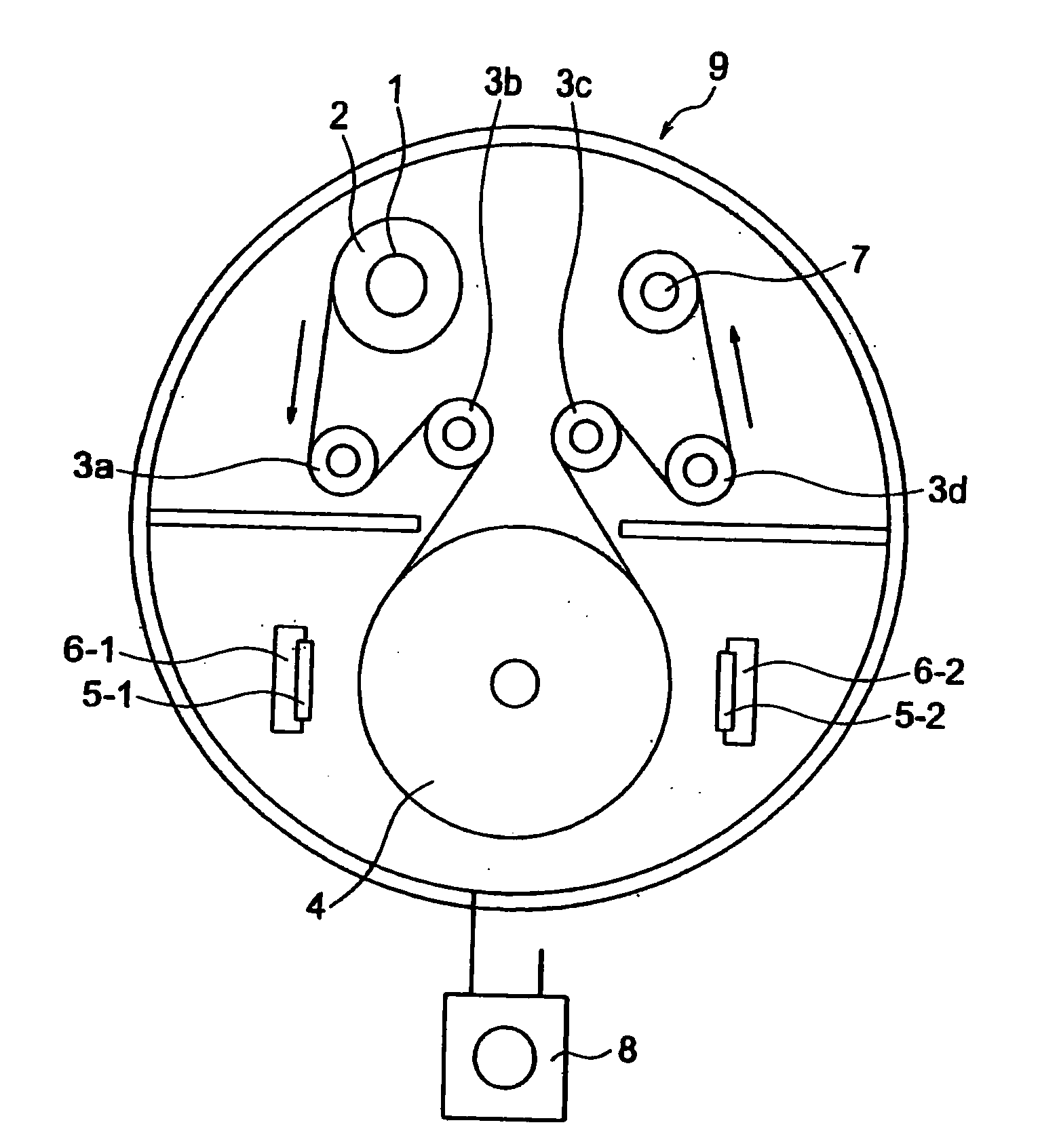
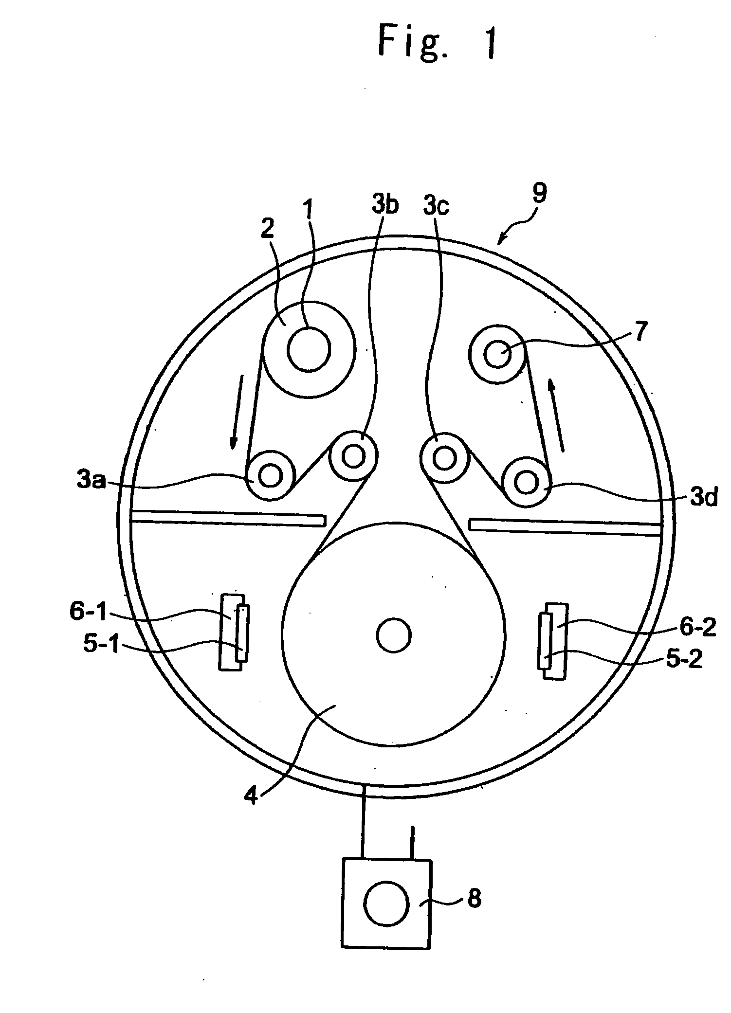
[0081] Pellets of a norbornene-based polymer [manufactured by ZEON Corporation; “ZEONOR 1420”; Tg: 135° C.; the saturated water absorption: smaller than 0.01% by weight] were dried at 70° C. for 2 hours by a heated air drier through which the air was passed. Using the dried pellets, a film having a thickness of 40 μm and a length of 300 m was formed by extrusion using a melt extruder of the T-die type having a melt mixer for resins and equipped with a screw of 65 mmφ under the condition of a temperature of the melt resin of 240° C. and a width of the T-die of 500 mm. The obtained long sheet of the film was wound to obtain a roll.

[0082] The film prepared from the norbornene-based polymer (referred to as Film A, hereinafter) had a photoelastic coefficient of 6.3×10⁻¹² Pa−1, a saturated water absorption of 0.01% by weight and a content of volatile components smaller than 0.01% by weight.

preparation example 2

Preparation of a Primer Solution

[0083] A hydrogenation product of a styrene-butadiene-styrene block copolymer modified with maleic anhydride [manufactured by ASAHI KASEI Corporation; TUFTECH M1913; the melt index: 4.0 g / 10 minutes at 200° C. under a load of 49 N; the content of the styrene block: 30% by weight; the degree of hydrogenation: 80% or greater; the amount of addition of maleic anhydride: 2%] in an amount of 2 parts by weight was dissolved into a mixed solvent of 8 parts by weight of xylene and 40 parts by weight of methyl isobutyl ketone. The obtained solution was filtered through a filter made of polytetrafluoroethylene and having a pore diameter of 1 μm, and the complete solution alone was used as the primer solution.

preparation example 3

Preparation of a Hard Coat Material

[0084] A hexafunctional urethane acrylate oligomer [manufactured by SHIN NAKAMURA Chemical Co., Ltd.; the trade name: “NK OLIGO U-6HA”] in an amount of 30 parts by weight, 40 parts by weight of butyl acrylate, 30 parts by weight of isobornyl methacrylate [manufactured by SHIN NAKAMURA KAGAKU Co., Ltd.; the trade name: “NK ESTER IB”] and 10 parts by weight of a photopolymerization initiator (2,2-dimethoxy-1,2-diphenylethan-1-one) were mixed by a homogenizer, and a hard coat material comprising a resin composition of the ultraviolet curing type was prepared.


PUM

PropertyMeasurementUnit
Fractionaaaaaaaaaa
Percent by massaaaaaaaaaa
Electrical resistanceaaaaaaaaaa

Abstract

A protective film for polarizing plates comprises an antireflection layer (reflectance≦0.5% at 550 nm) having high refractivity layers and low refractivity layers alternately laminated on a thermoplastic film (photoelastic coefficient≦9.0×10⁻¹² Pa−1, saturated water absorption<0.05% by weight) and has 0.3 or smaller standard deviation of S, which is obtained by obtaining a reflectance R(λ) at a wavelength λ while λ is increased from 380 to 780 nm by an increment Δλ of 1 nm, calculating S: S=∑λ=380780⁢Δ⁢ ⁢λ·R⁡(λ)(1)and calculating the standard deviation at 10 points randomly selected within 100 cm2 on the surface of the film. When the film is disposed on the surface of the visual side of a display device such as a liquid crystal display device, the film prevents reflection and suppresses fluctuation in distributions of luminance and color difference due to the uniform spectral reflectance within the surface of the film.

Description

TECHNICAL FIELD [0001] The present invention relates to a protective film for polarizing plates. More particularly, the present invention relates to a protective film for polarizing plates which has a uniform spectral reflectance within the surface of the film and is provided with the function of preventing reflection which can suppress fluctuation in the distribution of luminance and the distribution of color difference when the film is disposed on the surface of the visual side of a display device such as a liquid crystal display device. BACKGROUND ART [0002] Recently, planar display devices such as liquid crystal display devices and organic electroluminescence devices are highlighted as the electronic display device. Since the liquid crystal display device has a smaller size and is more compact than the cathode ray tube display device, various appliances equipped with the liquid crystal display device are being widely used. For example, the demand for downsizing various appliance...

Claims


Application Information

Patent Timeline
IPC IPC(8): G11B5/64B32B7/02G02B1/10G02B1/11G02B1/116G02B1/14G02B5/30G02F1/1335
CPCG02B1/105G02B1/115G02F1/133502G02F2201/38Y10T428/1041Y10T428/269Y10T428/24355Y10T428/26G02F2201/50Y10T428/31855Y10T428/31504G02B1/14C09K2323/031
Inventor YOSHITOMI, YASUMASATOYOSHIMA, TETSUYAYOSHIHARA, MASANORI
Owner ZEON CORP
Why Eureka
Try Eureka