Optical film, method for producing the same and polarizing plate using the same

a technology of optical film and polarizing plate, applied in the field of optical film, can solve the problems of large equipment required for drying solvent, insufficient uniformity of film thickness and retardation value, and insufficient uniformity of observing field,

Inactive Publication Date: 2006-09-28
KONICA MINOLTA OPTO
View PDF3 Cites 22 Cited by
  • Summary
  • Abstract
  • Description
  • Claims
  • Application Information

AI Technical Summary

Problems solved by technology

However, the method has a problem such as that the large equipment is necessary for drying the solvent.
This method has an advantage that the equipment can be made relatively compact because the drying of solvent is not necessary, while having a disadvantage in that the obtained film is not fully satisfactory in the uniformity in the film thickness and in the retardation values.
However, a problem is posed that, when the films (unstretched films) obtained by the methods described in Patent Documents 1 and 2 are each stretched in the lateral direction and when the film is observed under crossed nicols condition, the darkness of the observing field is not uniform and unevenness of the darkness is observed.
Moreover, a problem is posed on such the methods that the thickness distribution in the lateral direction of the stretched film cannot be controlled because the thickness profile of the film in the lateral direction is decided by the distance between the cooling roller and the endless belt or the space between the cooling drums.
A problem is also posed that the darkness of the observing field is not uniform and unevenness of the darkness is observed when the film (unstretched film) obtained by the method described in Patent Document 3 is stretched in the lateral direction and observed under crossed nicols condition.
Moreover, the thickness profile of the film cannot be freely controlled by the method since the resin film is in contact with the drum at a temperature near the glass transition point (Tg) of the resin.
Regarding the method described in Patent document 4, a problem is posed that, when the distance between the cooling drum and the die is increased, undulation appears on the surface of the film in molten state, whereby flatness of the film deccreses.
The methods described in Patent Documents 5 and 6 are each the method for controlling the stretching conditions and the thickness, however, the control of the retardation of the film in the lateral direction has not been fully easy.
The method described in Patent Document 7 is a method to reduce the optical distortion at the central portion of the film while the film is formed by passing through two cooling rollers, however, it has not been fully easy to improve the uniformity in thickness or in retardation of the film.

Method used


Image

  • Optical film, method for producing the same and polarizing plate using the same
  • Optical film, method for producing the same and polarizing plate using the same
  • Optical film, method for producing the same and polarizing plate using the same

Examples


example 1

[0136]

Cellulose acetate propionate (Acetyl group100parts by weightsubstitution degree: 1.95, propionyl groupsubstitution degree: 0.7, Number average molecular weight: 75,000, Dried in vacuum for 24hours at 60° C.)Triphenyl phosphate10parts by weightEthylphthalylethyl glycol2parts by weightTinuvin 109 (Ciba Specialty Chemicals0.5parts by weightCO., Ltd.)Tinuvin 171 (Ciba Specialty Chemicals 0.5parts by weightCO., Ltd.)Tinuvin 326 (Ciba Specialty Chemicals 0.3parts by weightCO., Ltd.)Antioxidant: 2.6-di-t-butyl-p-cresol +0.01parts by weightpentaerythrytol-tetrakis[3-(3,5-di-t-butyl-4-hydroxyphenyl) propionate]

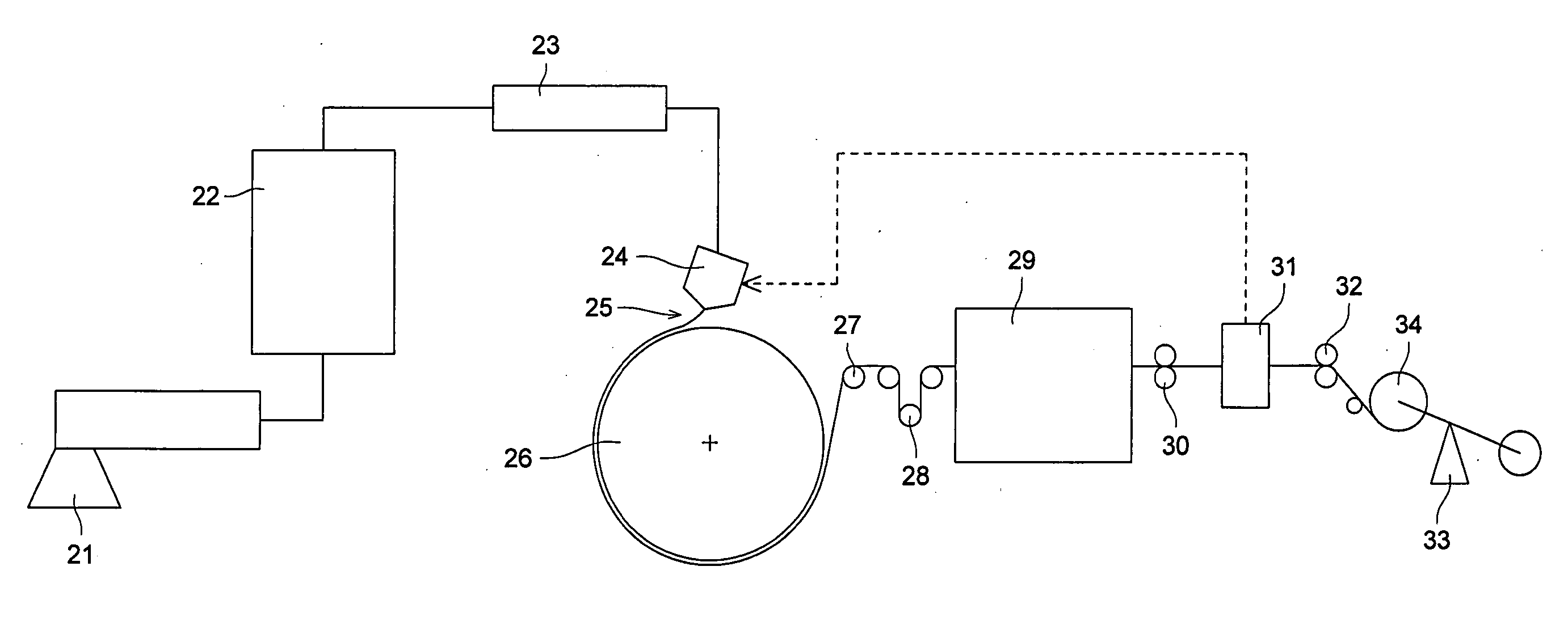
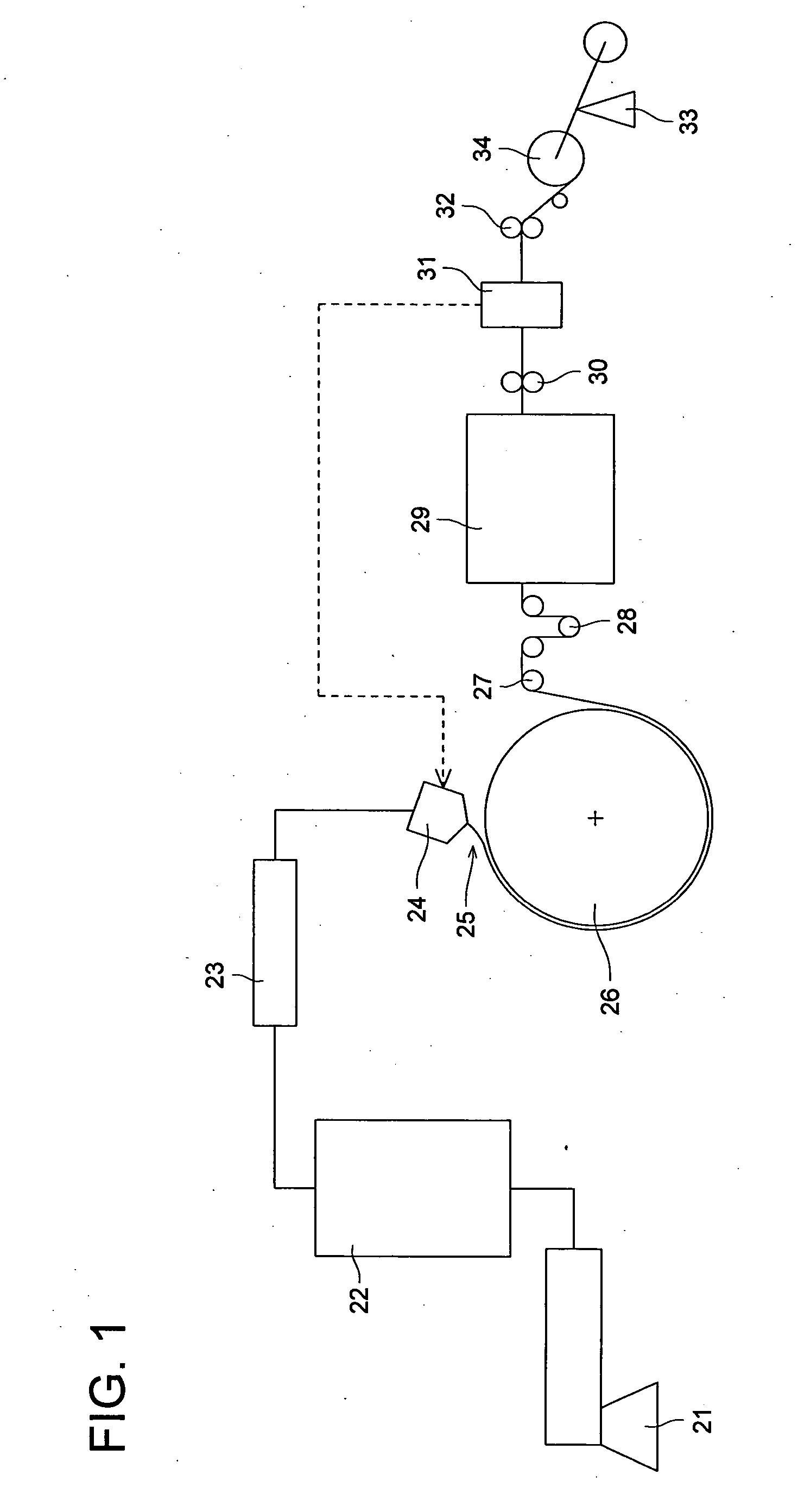
[0137] The above mixture was molten and mixed using the two-axis extruder 21 in FIG. 1 to form pellets. The pellets were molten at 250° C. and extruded through the T-die 24 into a form of film onto the cooling drum 26 held at 30° C. The width of the cooling drum 26 was 1950 mm.

[0138] The cooling drum 26 was divided into regions of: (i) each ⅕ of the width from each of the side e...

example 2

[0159] Poly vinyl alcohol having a thickness of 120 μm was immersed in 100 parts by weight of an aqueous solution containing l part by weight of iodine-and 4 parts by weight of boric acid and stretched for 4 times at 40° C. to prepare a polarization film.

[0160] Besides, Konica Minolta TAC having a thickness 80 μm, cellulose triacetate film manufactured by Konica Minolta Opto Inc., was immersed in an aqueous solution of sodium hydroxide having a concentration of 2 moles / liter for 2 minutes at 60° C. and dried for 10 minutes at 100° C. to prepare alkali saponified cellulose triacetate film for the protective film.

[0161] Thus obtained polarization film was pasted with the above triacetate film by an adhesive of 5% aqueous solution of completely saponified poly vinyl alcohol so as to prepare a polarizing plate having the protective film on one side thereof.

[0162] The optical films obtained in Example 1 were each subjected to corona treatment of 50 dyn / cm and pasted onto the side with...


PUM

PropertyMeasurementUnit
widthaaaaaaaaaa
temperatureaaaaaaaaaa
thicknessaaaaaaaaaa

Abstract

A method for producing an optical film comprising the steps of: (i) melt casting a cellulose ester resin or a cycloolefin resin by extruding melt of the cellulose ester resin or the cycloolefin resin from a die onto a roll-shaped cooling drum; (ii) cooling and solidifying the extruded melt to form a film; (iii) stretching the film in a lateral direction of the film; and (iv) winding the film in a roll, wherein the cooling drum has plural regions divided predeterminedly in an axis direction of the cooling drum, a temperature of each region being independently controlled.

Description

[0001] This application is based on Japanese Patent Application No. 2005-092168 filed on Mar. 28, 2005 in Japanese Patent Office, the entire content of which is hereby incorporated by reference. FIELD OF THE INVENTION [0002] The present invention relates to an optical film which can be applied for various kinds of functional film such as a polarizing plate protective film, a retardation film and a viewing angle extending film used for a liquid crystal displaying (LCD), an antireflection film for a plasma display, as well as a functional film for an organic EL display, and also relates to a method for producing such an optical film and to a polarizing plate using the optical film. BACKGROUND OF THE INVENTION [0003] Liquid crystal display has been widely applied as a monitor since it is space saving as well as energy saving compared to the conventional CRT display. Moreover, liquid crystal display is also becoming popular as a TV. Various kinds of optical films such as a polarization ...

Claims


Application Information

Patent Timeline
Patent Type & Authority Applications(United States)
IPC IPC(8): B29D7/01B29C47/92B29C47/88B29C48/92
CPCB29C41/26B29C47/92B29C47/0021B29C47/0057B29C47/14B29C47/8845B29C55/08B29C2947/92019B29C2947/92123B29C2947/92152B29C2947/92209B29C2947/92314B29C2947/92361B29C2947/92428B29C2947/92438B29K2001/00B29K2001/12B29K2029/00B29K2069/00B29K2077/00B29K2079/08B29K2105/256B29K2995/0018B29K2995/0034G02B5/3016B29C47/0004B29C48/92B29C2948/92209B29C48/022B29C48/08B29C48/0018B29C48/305B29C48/914B29C2948/92019B29C2948/92123B29C2948/92152B29C2948/92314B29C2948/92361B29C2948/92428B29C2948/92438B62D1/10B62D1/043B62D1/16B62D5/12B62D5/22B60Y2400/301B60Y2400/70
Inventor KAZAMA, KENICHI
Owner KONICA MINOLTA OPTO
Why Eureka
Try Eureka