Electrophotographic photoreceptor, image forming method and image forming apparatus utilizing the same

a photoreceptor and photoreceptor technology, applied in the field of electrostatic photoreceptors, can solve the problems of deterioration of electrostatic characteristics of photoreceptors, generation of abrasion on the surface of photoreceptors, and the insufficient durability of photoreceptors, and achieve stable charging voltage and high sensitivity and mechanical strength.

Inactive Publication Date: 2006-09-28
KONICA MINOLTA BUSINESS TECH INC
View PDF13 Cites 4 Cited by
  • Summary
  • Abstract
  • Description
  • Claims
  • Application Information

AI Technical Summary

Benefits of technology

[0016] An object of this invention is to provide an electrophotographic photoreceptor, which can maintain high sensitivity and mechanical strength even in a long term use, as well as gives stable charging voltage without an image flow and deterioration against gas, an image forming apparatus and a process cartridge utilizing the same.

Problems solved by technology

However, disadvantages are problems of deterioration of electrostatic characteristics of a photoreceptor and generation of abrasion on the surface of the photoreceptor, at the time of making a large number of copies, due to poor mechanical strength and chemical durability.
However, since it is not advantageous for maintaining high image quality when a charge transfer layer is made to be too thick, heretofore, already proposed has been an organic photoreceptor, in which a charge transfer layer is made thinner to prevent diffusion of an electrostatic latent image, in such as JP-A No. 5-119503 (hereinafter, JP-A refers to Japanese Patent Publication Open to Public Inspection).
However, these proposed organic photoreceptors still have not sufficiently answered the requirements of durability of a photoreceptor and higher quality images.
However, in these abrasion resistance improvement techniques, there is observed a tendency of deterioration in image quality, particularly, in sharpness when repeated image formation is performed to provide many sheets of copied images.
These were effective to improve characteristics of an organic photoreceptor, however, nowadays, the required level of capability improvement with respect to an organic photoreceptor is high and they cannot be said satisfactory in this sense.
Particularly, by employing all of the above-described improvement techniques, an effect accumulating these techniques cannot necessarily be obtained and even they may cancel functions each other by combination use of these techniques, as a result, it has been proved how to combine these techniques is a big problem.

Method used


Image

  • Electrophotographic photoreceptor, image forming method and image forming apparatus utilizing the same
  • Electrophotographic photoreceptor, image forming method and image forming apparatus utilizing the same
  • Electrophotographic photoreceptor, image forming method and image forming apparatus utilizing the same

Examples


example 1

1-1>.

[0108] An intermediate layer, comprising polyamide resin and having a thickness of 0.3 μm, was provided on an aluminum drum having a diameter of 100 mm. Next, a coating solution which was comprised of 30 weight parts of oxytitanium phthalocyanine (CGM-1), which is provided with a peaks at such as 9.5°, 9.7°, 11.6°, 15.0° and 24.1° in addition to the maximum peak at 27.3°, in a X-ray diffraction spectrum employing CuKα characteristic X-ray, 10 weight parts of butyral resin “ESLEC B (BX-L)” (manufactured by Sekisui Chemical Co., Ltd.) and 1600 weight parts of methyl ethyl ketone, was immersion coated on the aforesaid intermediate layer, followed by being dried to form a CGL having a layer thickness of 0.3 μm.

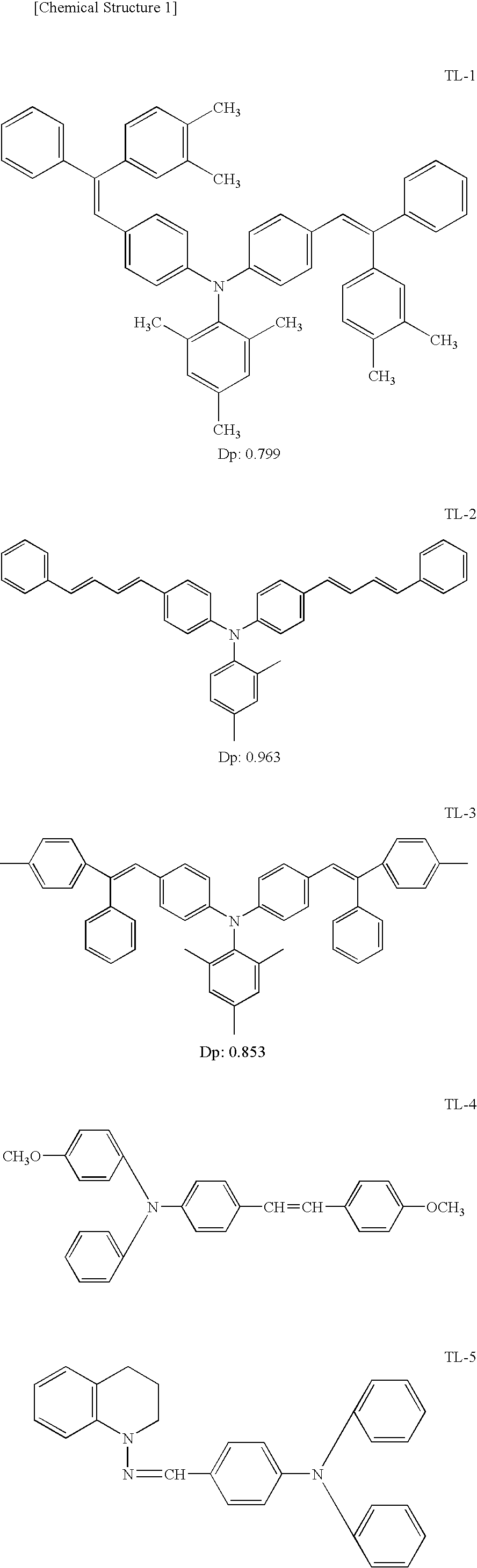
[0109] Next, a lower (support side) CTL coating solution was prepared by dissolving 500 weight parts of example compound (TL-1) as a CTM and 600 weight parts of polycarbonate resin “EUPILON Z300” (manufactured by Mitsubishi Gas Chemical Co., Inc.) in 3000 weight parts of a ...

example 2

2-1>

Intermediate Layer:

[0130] An aluminum drum having a diameter of 100 mm was coated with intermediate layer coating liquid by dip coating method, and dried with 120° C. for 30 min. to form an intermediate layer having 1.0 mm dry thickness. The dispersion liquid described below was diluted double with the same mixing solvent, left at rest over night, and filtered with RIGIMESH filter (MADE BY Nihon Pall Ltd., Filtering accuracy: 5 μm, Pressure: 50 kPa) to form the intermediate coating liquid.

[0131] Binder resin: Polyamide, 1 part (1.00 part per volume);

[0132] Rutile type titanium oxide A1 (primary particle diameter, 35 nm; surface treatment was applied with copolymer of methylhydrogen siloxane and dimethyl siloxane (mol ratio, 1:1) of 5 weight % of the titanium oxide A1), 3.5 part (1.0 part per volume);

[0133] Ethanol / n-propyl-alcohol / THF (=45 / 20 / 30 weight ratio), 10 parts;

[0134] Above described materials were mixed and dispersed with the use of sand-mill dispersion machine fo...

example 3

3-1>

[0140] An aluminum drum having a diameter of 100mm of the photoreceptor 2-1 was replaced to the aluminum drum having a diameter of 60 mm, further the lower CTL and the upper CTL were prepared with the coating liquid below. Other components and structures were the same as those of the photoreceptor 2-1.

Under Charge Transfer Layer(CTL):Charge transfer material (TL-1)675partsPolycarbonate (EUPILON Z300: made by Mitsubishi Gas600partsChemical Company, Inc.)THF / toluene (weight ratio: 7 / 3)3000partsSilicone oil (KF-54: made by Shin-Etu Chemical Co.,1partLtd.)

[0141] The above ingredients were mixed and solved to prepare the under CTL coating liquid 2. This coating liquid was coated on the above-described CGL with dip coating method, dried 70 min. with 110° C., and the under layer of CTL having 15.0 μm dry thickness was formed.

Upper Charge Transfer Layer (CTL):Charge transfer material (TS-1)220partsPolycarbonate (EUPILON Z800: made by Mitsubishi Gas600partsChemical Company, Inc.)THF / ...


PUM

PropertyMeasurementUnit
number average primary particle diameteraaaaaaaaaa
thicknessaaaaaaaaaa
number average primary particle diameteraaaaaaaaaa

Abstract

An electrophotographic photoreceptor including a charge generating layer and a charge transfer layer accumulated on a support member, the charge transfer layer including at least two layers of a support side layer and a surface side layer, wherein the support side layer contains A mol/cm3 of charge mol/cm3 of charge transfer material having a dipolar moment of not more than 0.75 and inorganic particles having a number average primary particle diameter of 3-150 nm, wherein A and B satisfies relations of (1) and (2),
9.0×10⁻⁴>A>3.0×10⁻⁴   (1)
8.0×10⁻⁴>B>2.0×10⁻⁵   (2)

Description

BACKGROUND OF THE INVENTION [0001] The present invention relates to an electrophotographic photoreceptor; an image forming method and an image forming apparatus and a process cartridge utilizing the same. [0002] In recent years, an organic photoreceptor is widely utilized as an electrophotographic photoreceptor. An organic photoreceptor, in contrast to other photoreceptors, is provided with advantageous points of enabling such as easy development of materials corresponding to various types of exposure light sources from visible light to infrared light, selection of materials without environmental pollution, and lower manufacturing cost. However, disadvantages are problems of deterioration of electrostatic characteristics of a photoreceptor and generation of abrasion on the surface of the photoreceptor, at the time of making a large number of copies, due to poor mechanical strength and chemical durability. [0003] That is, since the surface of a photoreceptor is directly applied with ...

Claims


Application Information

Patent Timeline
Patent Type & Authority Applications(United States)
IPC IPC(8): G03G9/087
CPCG03G5/047G03G5/0507G03G5/0564G03G5/0605G03G5/0607G03G5/0614G03G5/0616G03G5/0629G03G5/0666G03G5/0668G03G5/0672G03G5/14704G03G5/14713G03G5/14756G03G5/06144G03G5/061443G03G5/06145G03G5/06147G03G5/061473
Inventor YAMANE, CHIGUSAINAGAKI, KEIICHIOGURA, KUNIHIRO
Owner KONICA MINOLTA BUSINESS TECH INC
Why Eureka
Try Eureka