Hemodialysis access with on-off functionality

a technology of hemodialysis and functionality, applied in the field of hemodialysis, can solve the problems of increasing the burden of modern society, the stenosis of the vessel, and the collapse of the vessel, so as to prevent the formation of a stenosis, reduce the stenosis, and prevent the formation of localized thrombosis or adhesion

Inactive Publication Date: 2006-10-05
GERTNER MICHAEL
View PDF58 Cites 36 Cited by
  • Summary
  • Abstract
  • Description
  • Claims
  • Application Information

AI Technical Summary

Benefits of technology

[0060] Another mode of this aspect includes coupling sufficient energy between the treatment assembly and the area to substantially prevent formation of a stenosis at the location.
[0061] Another mode of this aspect includes coupling sufficient energy between the treatment assembly and the area to substantially reduce a stenosis at the location.
[0062] Another mode of this aspect includes coupling sufficient energy between the treatment assembly and the area to substantially prevent localized thrombus formation or adhesion at the location.
[0063] Another mode of this aspect includes coupling sufficient energy between the treatment assembly and the area to substantially reduce a localized thrombus at the location.

Problems solved by technology

Renal disease and deficiency has long been a significant problem that continues to plague an enormous population of patients, and the related cost of treatment continues as an ever growing burden on modern society as a whole.
Otherwise, the vessel will collapse as the dialysis machine pulls out blood.
In general, these devices are inserted into the subclavian or internal jugular veins, communicate exteriorly of the patient, and at best are considered “semi-permanent” devices in that their longevity is limited, generally lasting up to a typical maximum of about 4 months.
A damaging process called “intimal hyperplasia” often begins at the time of surgery, and continues undisturbed in most cases until it leads ultimately to failure of the access fistula.
The major problem in permanent dialysis access is the longevity of the fistula.
This usually leads to substantial morbidity, cost, and physician frustration; and in 1993 vascular access was described as a $1 billion problem.
Many patients die secondary to lack of access.
Though this number may have decreased in recent years as devices and techniques improve, it still remains a significant issue that deserves attention.
The placement of the needle is not standardized with respect to the fistula, being placed in a different spot in the graft each time, resulting in disruption of the ultrastructure of the material over time.
Furthermore, at least about 10 minutes of pressure is usually required to prevent hematoma formation at the access site, which may itself lead to a thrombosis.
However, this particular technique suffers by the rapid clearance that the contrast agent may experience from the area in a blood flow environment.
Also, this example does not provide for a device or method for using energy delivery for regular preventative maintenance of fistula patency, such as to prevent thrombus formation or adhesion in the fistula, or to prevent or treat neo-intimal hyperplasia.
However, this example does not provide for prevention or removal of thrombus.
In addition, the internal catheter aspect of this example requires an active ultrasound energy source to be located on the catheter itself, which results in significant complexity and cost that may be prohibitive to regular maintenance use as a disposable assembly.
The active source in addition may limit the ability to make such a catheter sufficiently small to be inserted into a fistula lumen through certain needles such as certain hemodialysis needles.
In addition to the limitations of the previous ultrasound energy delivery examples just described, they also do not provide for a system or method for actuating an treatment device within a fistula to deliver vibratory or other energy to tissues by exposing the treatment assembly to an applied energy field from a remotely located energy source outside of the fistula, such as externally of the patient and transcutaneously across a skin barrier.
Nor do these previous techniques provide for the ability to deliver an energy delivery treatment assembly into a fistula through a hemodialysis needle such that additional punctures of the fistula are not required.
Still further, these previous techniques also do not provide for an energy delivery treatment assembly secured to and implanted with a fistula graft.
Nor do these techniques provide for other forms of energy delivery than ultrasound into problematic areas associated with fistula grafts in order to provide therapy to a patient.
However, the doppler device and method of this example does not deliver energy into the fistula in order to affect treatment or prevention of stenosis associated with the fistula.
Moreover, there is no provision for applying an energy field from outside of a fistula to actuate energy delivery from a treatment assembly located within the fistula.
Despite certain advances that may have been provided by various of the disclosures cited above, there are still many needs that have not yet been adequately met.

Method used


Image

  • Hemodialysis access with on-off functionality
  • Hemodialysis access with on-off functionality
  • Hemodialysis access with on-off functionality

Examples


Embodiment Construction

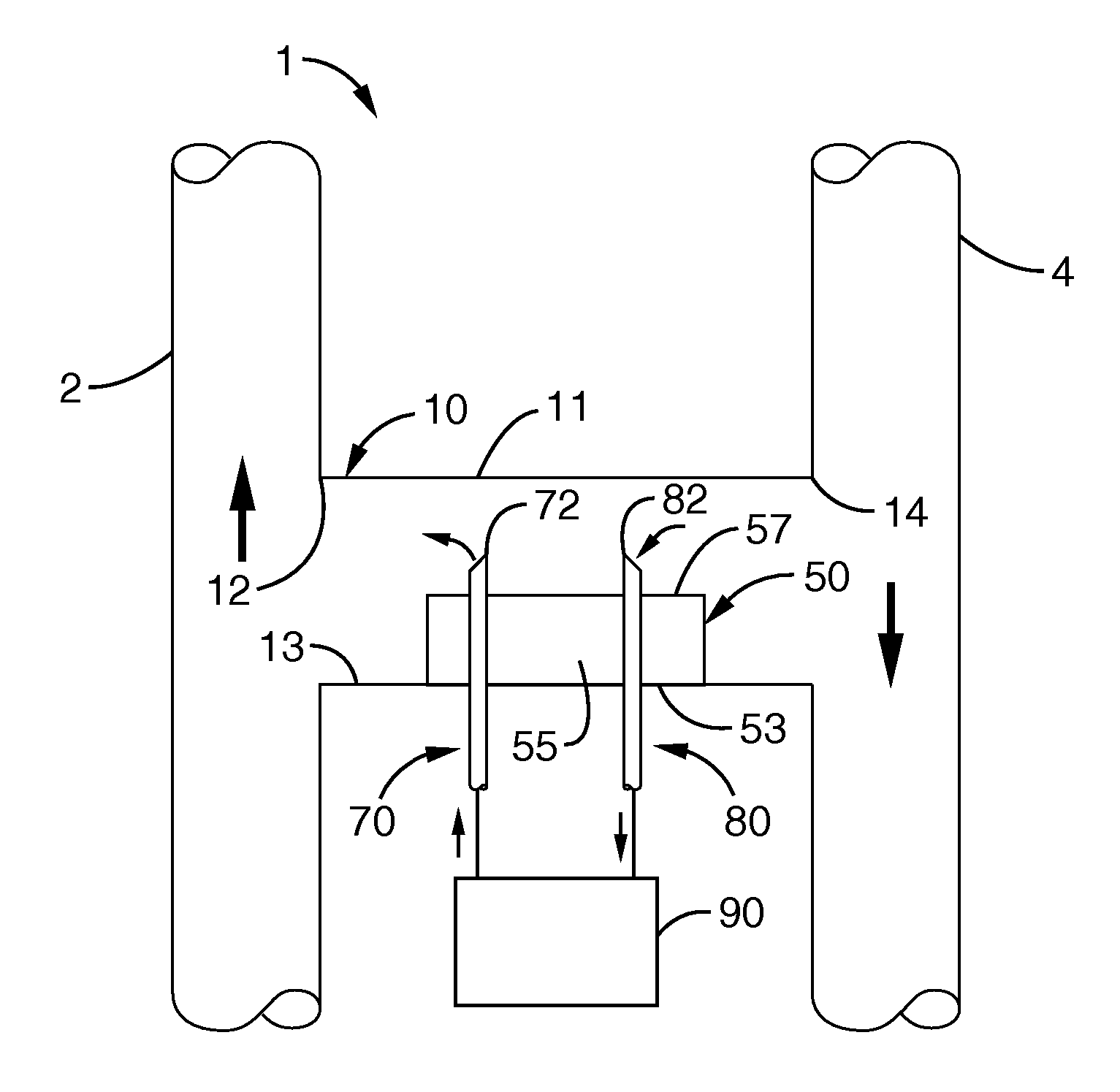
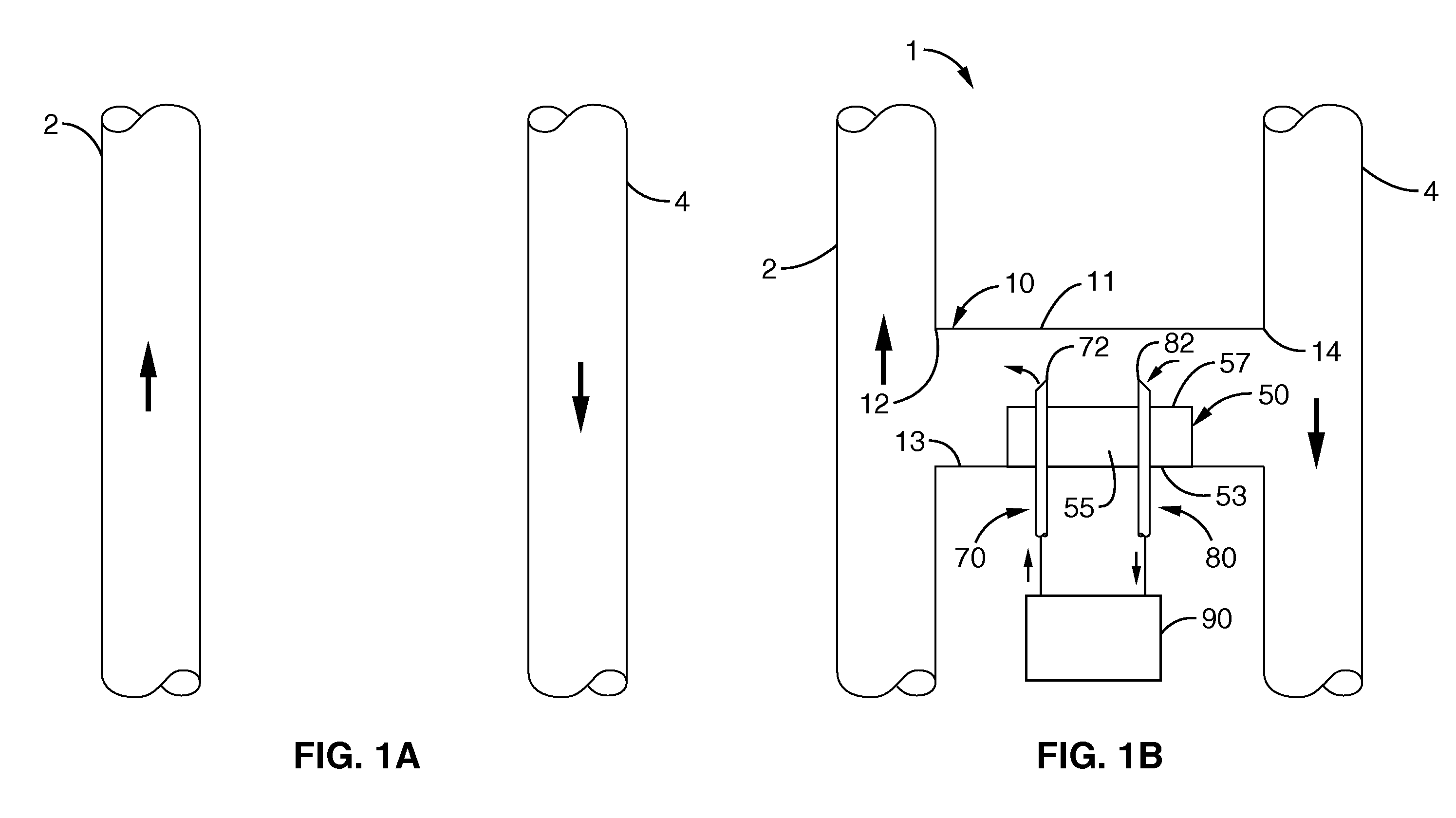
[0112] It is to be appreciated that the present invention in one regard provides a system with at least one device that is adapted to increase the long-term patency for an AV-fistula, and therefore longevity of dialysis access, with respect to a vein 2 and artery 4 in a patient, which are shown in FIG. 1A for the purpose of reference prior to beginning a hemodialysis procedure with the system and method of the present invention.

[0113] AV-Fistula with Valved Needle Access & Controlled Drug Delivery

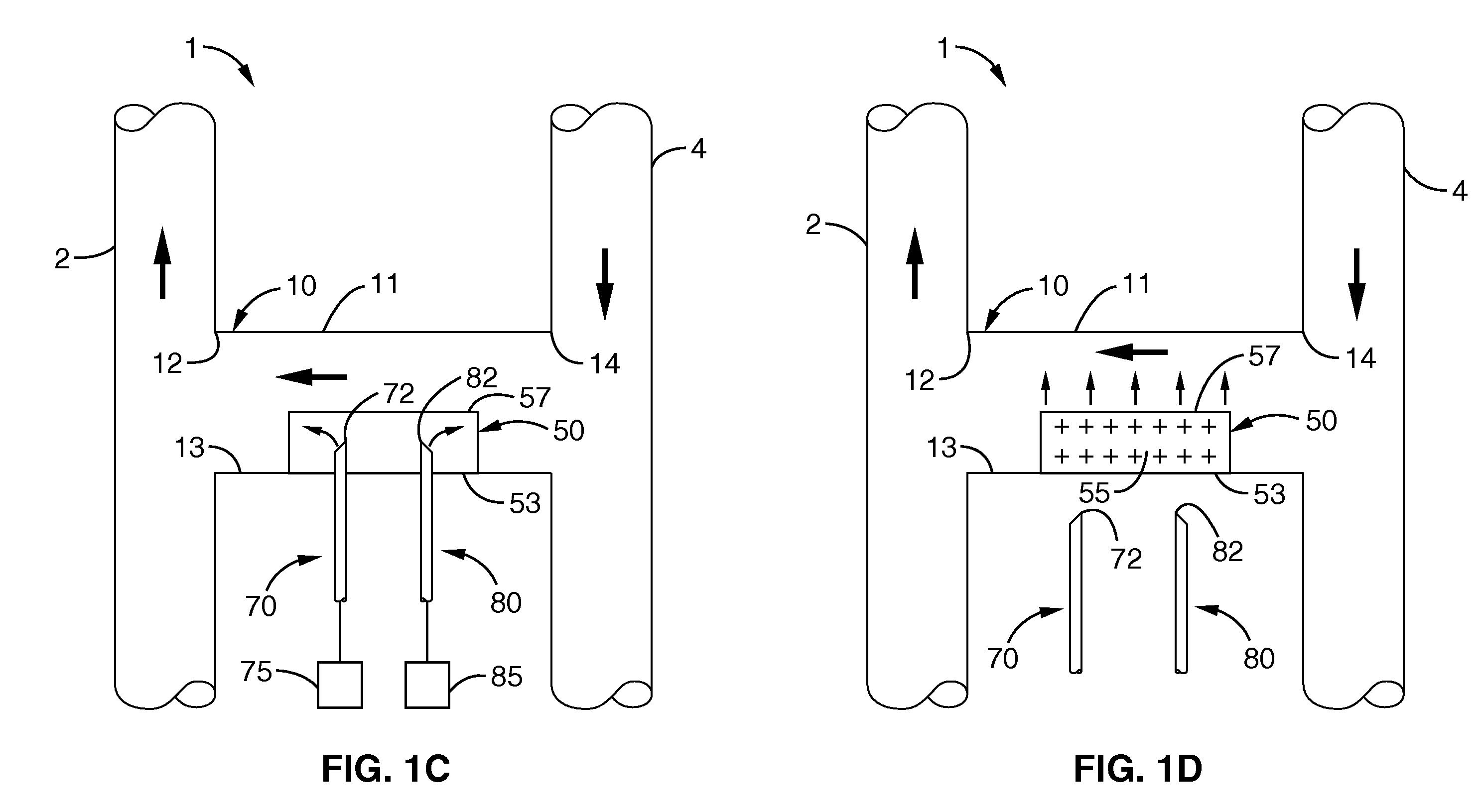
[0114] According therefore to one beneficial embodiment, FIG. 1 shows one hemodialysis system 1 of the invention with an AV-fistula 10 that extends between two anastomosis sites 12, 14 along vein 12 and artery 14, respectively. Along a wall of fistula 10, and generally flush with an outer surface thereof, is a localized valve system 50.

[0115] Valve system 50 may be integrated into fistula 10, such as in a pre-packaged, sterilized assembly. However, it is further contemplated that valve s...


PUM


Abstract

A treatment assembly is positioned along an AV-fistula and couples therapeutic energy to an adjacent area due to a material response to an applied energy field from a remotely located energy source. The treatment assembly may be delivered into the fistula through a hemodialysis needle, or may be secured to the fistula graft itself and implanted therewith within a patient. A cover provides a shield between an anastomosis area and blood flow. Another AV-fistula includes a valved reservoir that receives a fluid agent from a hemodialysis needle while moving the needle into or from the fistula; the agent leaks from the reservoir into the fistula lumen. Another valved fistula is adjustable between an open condition and closed conditions during and between hemodialysis treatments, respectively. Another AV-fistula has a bladder reservoir coupled to a second refillable fluid reservoir and is adapted to locally deliver a therapeutic agent into the fistula lumen.

Description

CROSS-REFERENCE TO RELATED APPLICATIONS [0001] This application is a divisional of U.S. application Ser. No. 10 / 177,721, filed on Jun. 20, 2002, incorporated herein by reference, which claims priority from U.S. provisional application Ser. No. 60 / 299,223 filed on Jun. 20, 2001, incorporated herein by reference.STATEMENT REGARDING FEDERALLY SPONSORED RESEARCH OR DEVELOPMENT [0002] Not Applicable REFERENCE TO A COMPUTER PROGRAM APPENDIX [0003] Not Applicable BACKGROUND OF THE INVENTION [0004] 1. Field of the Invention [0005] This invention pertains generally to hemodialysis, and more particularly to hemodialysis systems and methods including A-V fistula grafts, A-V fistula graft treatment systems, systems for treating a condition associated with an AV-fistula graft, and an A-V fistula graft systems. [0006] 2. Description of the Background Art [0007] Renal disease and deficiency has long been a significant problem that continues to plague an enormous population of patients, and the rel...

Claims


Application Information

Patent Timeline
Patent Type & Authority Applications(United States)
IPC IPC(8): A61M5/00A61F2/06A61M1/16A61M1/36A61M39/10
CPCA61F2/06A61M1/16A61M1/3672A61M1/3653A61M1/3655A61M1/36A61M1/3673A61M1/3659A61M1/3661
Inventor GERTNER, MICHAEL
Owner GERTNER MICHAEL
Why Eureka
Try Eureka