Heat and electromagnetic wave generator

a generator and heat technology, applied in the field of electrochemical cells, can solve the problems that neither batteries nor electrolytic cells have historically produced large quantities of heat, and achieve the effect of optimizing the heat release of the electrolytic cell

Inactive Publication Date: 2006-10-12
CRAVENS DENNIS J
View PDF0 Cites 4 Cited by
  • Summary
  • Abstract
  • Description
  • Claims
  • Application Information

AI Technical Summary

Benefits of technology

[0006] The system is an electrolytic cell and system for electrolysizing and / or heating a liquid electrolyte containing water having a conductive salt in solution in contact with a plurality of electrodes so that ions can be formed and flow between the electrodes. The material used for the construction of the electrodes is chosen to optimize heat release from the electrolytic cell. The mode of operation of the electrolytic cell is designed so as to assure that some non-direct current components of the electrical flow pass through the surface of the electrodes. The electrolyte is chosen to produce free hydrogen ions that can flow to the surface of one or more electrodes under the imposed electrical currents. The design of the cell is chosen to allow recovery of heat production and possible gas production by the cell. The design and operating conditions allow for the production of electromagnetic radiation such as light.

Problems solved by technology

Neither batteries nor electrolytic cells have historically produced large quantities of heat.

Method used


Image

  • Heat and electromagnetic wave generator
  • Heat and electromagnetic wave generator
  • Heat and electromagnetic wave generator

Examples


Embodiment Construction

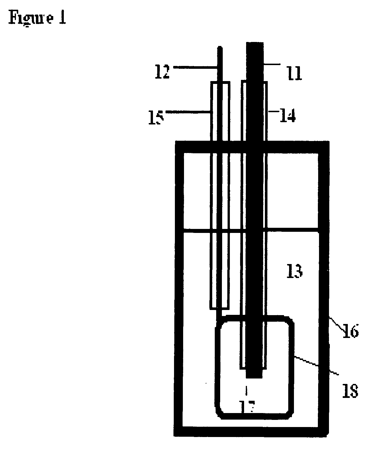
[0022]FIG. 1 illustrates the basic invention and its parts in one embodiment. In this concentric arrangement the central electrode, 11, is the smaller of two electrodes. This was formed by a 3 / 16 Thoriated tungsten welding rod with 2% Th. A second electrode, 12, is constructed of a Platinum gauze cylinder. Such Pt electrodes are well known in the art of electrochemistry. The Pt gauze cylinder was 1 cm in diameter and was designed so that it formed a cage, 18 around electrode 11. Both electrodes where insulated from unwanted chemical events by glass tubing, 14,15 that also supplied support and assure stable spacing between the two electrodes. The containment vessel, 16, in one embodiment was a 250 ml tall form beaker with a Teflon lid. For most operations, the vessel's construction is not critical, however, when the invention is used to generate various electromagnetic waves, it should be constructed from materials that freely pass the desired wavelength. For example, when long wave ...


PUM

PropertyMeasurementUnit
surface areaaaaaaaaaaa
diameteraaaaaaaaaa
voltagesaaaaaaaaaa

Abstract

The system presented is an electrolytic cell and system for electrolysizing and/or heating a fluid electrolyte containing hydrogen in one of its several isotopic and compound forms having a conductive solution electrolyte. The electrolytic cell includes an electrically conductive electrode prepared of selected metals and/or their alloys. The cell is designed to release heat and/or reaction products during or after operation. The several electrodes are placed in electrical contact with the fluid electrolyte so that current passes between the several electrodes and made to flow through the electrolyte. The currents and voltages used between the various electrodes are chosen to be high enough to form ionization of some selected parts of the fluid electrolyte and move hydrogen in one of its various forms to the surface of one or more electrodes. Several geometric configurations such as microspheres, multicells, concentric electrodes and other forms can be used. An electric power source in the system is connected across the electrodes whereby electrical current flows between the electrodes within the fluid electrolyte and supplying a large current density at one or more electrodes.

Description

CROSS REFERENCE TO RELATED APPLICATION [0001] Not Applicable STATEMENT REGARDING FEDERALLY SPONSORED RESEARCH OR DEVELOPMENT [0002] Not Applicable FIELD OF THE INVENTION [0003] This invention generally relates to electrochemical cells and more particularly to a thermo-electrochemical reactor where stored potential energy is activated by electrical charge and electrolysis of water and the production of useful amounts of heat. BACKGROUND OF INVENTION [0004] Batteries and electrolytic cells are two different types of electrochemical reactors. Batteries combine chemicals and convert potential chemical energy to electricity. Whereas, electrolytic cells use electricity to produce metals (e.g., copper and sodium) and gases (e.g., hydrogen and chlorine). Neither batteries nor electrolytic cells have historically produced large quantities of heat. In general, heating results from the joule heating of the electrolyte. In my prior U.S. Pat. No. 6,723,946 it was shown “that tungsten, nickel, pl...

Claims


Application Information

Patent Timeline
Patent Type & Authority Applications(United States)
IPC IPC(8): C25C7/02
CPCC25B1/00
Inventor CRAVENS, DENNIS J.
Owner CRAVENS DENNIS J
Why Eureka
Try Eureka