Phosphor for low-voltage electron beam, method of producing the same, and vacuum fluorescent display

a low-voltage electron beam and vacuum fluorescent technology, applied in the direction of tubes with screens, non-metal conductors, light-emitting coating applications, etc., can solve the problems of insufficient electrically conductive, complicated steps, and method that is unsuitable for mass production, so as to reduce the addition amount of electrically conductive oxide, increase the luminance of phosphor, and increase the surface energy

Inactive Publication Date: 2006-10-26
NORITAKE ITRON CORP +1
View PDF1 Cites 13 Cited by
  • Summary
  • Abstract
  • Description
  • Claims
  • Application Information

AI Technical Summary

Benefits of technology

[0013] The average diameter of the nano-particles of the electrically conductive oxide is in the range of 5 to 100 nm. Thus the nano-particle of the electrically conductive oxide has a much higher surface energy than those of conventional electrically conductive particles. When the nano-particles adhere to the surface of the phosphor for low-voltage electron beams, the surface energy thereof becomes low. Thereby the nano-particles do not separate from the surface of the phosphor. Consequently it is possible to decrease the addition amount of the electrically conductive oxide and increase the luminance of the phosphor.

Problems solved by technology

But phosphors ZnS, CaS, ZnGa2O4, SrTiO3, CaTiO3, ZnCdS, Y2O3, and Y2O2S are insufficiently electrically conductive.
This method solves the problem of the separation of the electrically conductive particles from the surface of the phosphor by uniformly adhering the electrically conductive particles to the surface of the phosphor with the water-soluble binder, but requires complicated steps.
Thus this method is unsuitable for a mass production.

Method used


Image

  • Phosphor for low-voltage electron beam, method of producing the same, and vacuum fluorescent display
  • Phosphor for low-voltage electron beam, method of producing the same, and vacuum fluorescent display
  • Phosphor for low-voltage electron beam, method of producing the same, and vacuum fluorescent display

Examples


examples 1 through 7

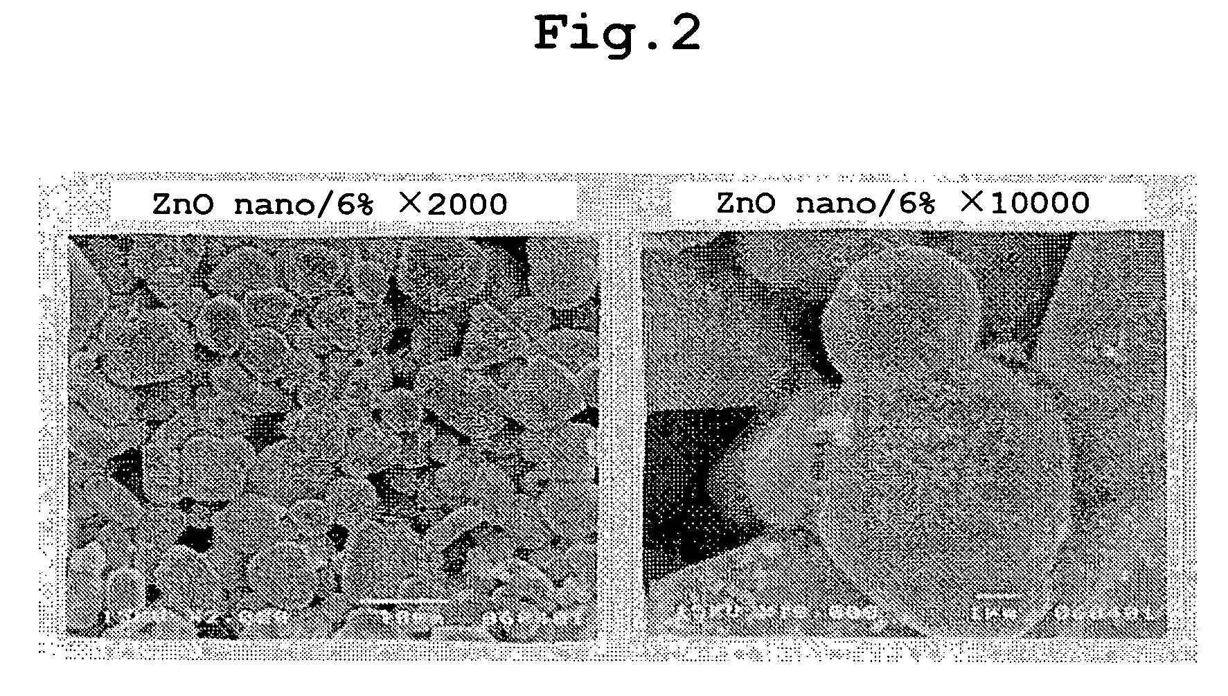
[0038] After nano-particles of zinc oxide (ZnO) having an average particle diameter of 50 nm was suspended in isopropyl alcohol (IPA) which is anorganic solvent, the zinc oxide was sufficiently dispersed by using an ultrasonic homogenizer of 300 W. After a predetermined amount of a phosphor consisting of ZnS:Ag, Cl having an average particle diameter of 3 μm was supplied to the dispersion, the nano-particles of the zinc oxide and particles of the phosphor consisting of ZnS:Ag, Cl were dispersed sufficiently by using the ultrasonic homogenizer. Thereafter the isopropyl alcohol was evaporated, while the suspended solution was being stirred with a rotary evaporator. As a result, a phosphor composed of ZnS:Cu, Al and the nano-particles of zinc oxide which firmly adhered to the surface of ZnS: Cu, Al was obtained.

[0039]FIG. 2 is an electron microscope photograph showing particles of the phosphor composed of the particles of ZnS:Cu, Al and the nano-particles of zinc oxide which adhered t...


PUM

PropertyMeasurementUnit
particle diameteraaaaaaaaaa
diameteraaaaaaaaaa
diameteraaaaaaaaaa

Abstract

Nano-particles of an electrically conductive oxide adhere to the surface of particles of a phosphor for low-voltage electron beams. The average diameter of nano-particles of the electrically conductive oxide is in the range of 5 to 100 nm. The weight percentage of the nano-particles of the electrically conductive oxide to the entire phosphor is 0.01 to 10. A vacuum fluorescent display uses the phosphor for low-voltage electron beams.

Description

BACKGROUND OF THE INVENTION [0001] The present invention relates to a phosphor for low-voltage electron beams, a method of producing the phosphor, and a vacuum fluorescent display using the phosphor. [0002] A phosphor for low-voltage electron beams for use in a vacuum fluorescent display, an FED, and the like are demanded to be electrically conductive, because it is necessary to escape incident electrons for exciting the phosphor from the surface of the phosphor to an anode. A green phosphor ZnO:Zn and a red phosphor SnO2 Eu are electrically conductive. But phosphors ZnS, CaS, ZnGa2O4, SrTiO3, CaTiO3, ZnCdS, Y2O3, and Y2O2S are insufficiently electrically conductive. Therefore electrically conductive materials not inhibiting the property of the phosphor are added as a conductivity-imparting agent to particles of the phosphor at 1 to 20 wt %. As the electrically conductive materials, electrically conductive oxides such as indium tin oxide (ITO), In2O3, SnO2, ZnO, and the like are use...

Claims


Application Information

Patent Timeline
Patent Type & Authority Applications(United States)
IPC IPC(8): C09K11/77C09K11/02
CPCC09K11/025Y10T428/2991C09K11/574C09K11/595C09K11/612C09K11/623C09K11/642C09K11/7703C09K11/7729C09K11/7789H01B1/08H01J29/20H01J2329/20Y10T428/2993C09K11/55H01J31/15H01J9/22
Inventor TSUJI, HITOSHIKITAMURA, HITOMI
Owner NORITAKE ITRON CORP
Why Eureka
Try Eureka