

Power unit device and power converter device
- Summary
- Abstract
- Description
- Claims
- Application Information
AI Technical Summary
Benefits of technology
Problems solved by technology
Method used
Image

Examples
first preferred embodiment
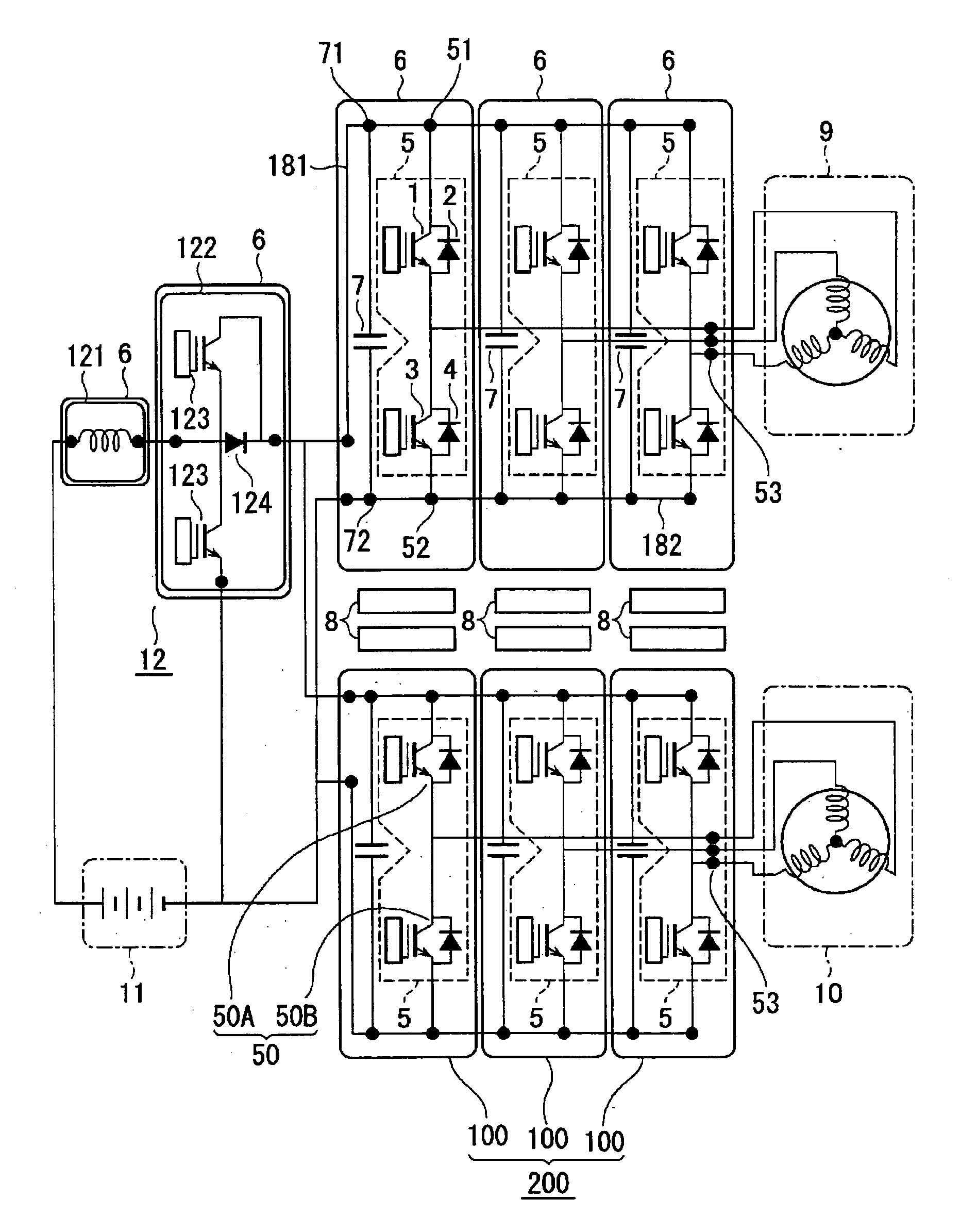
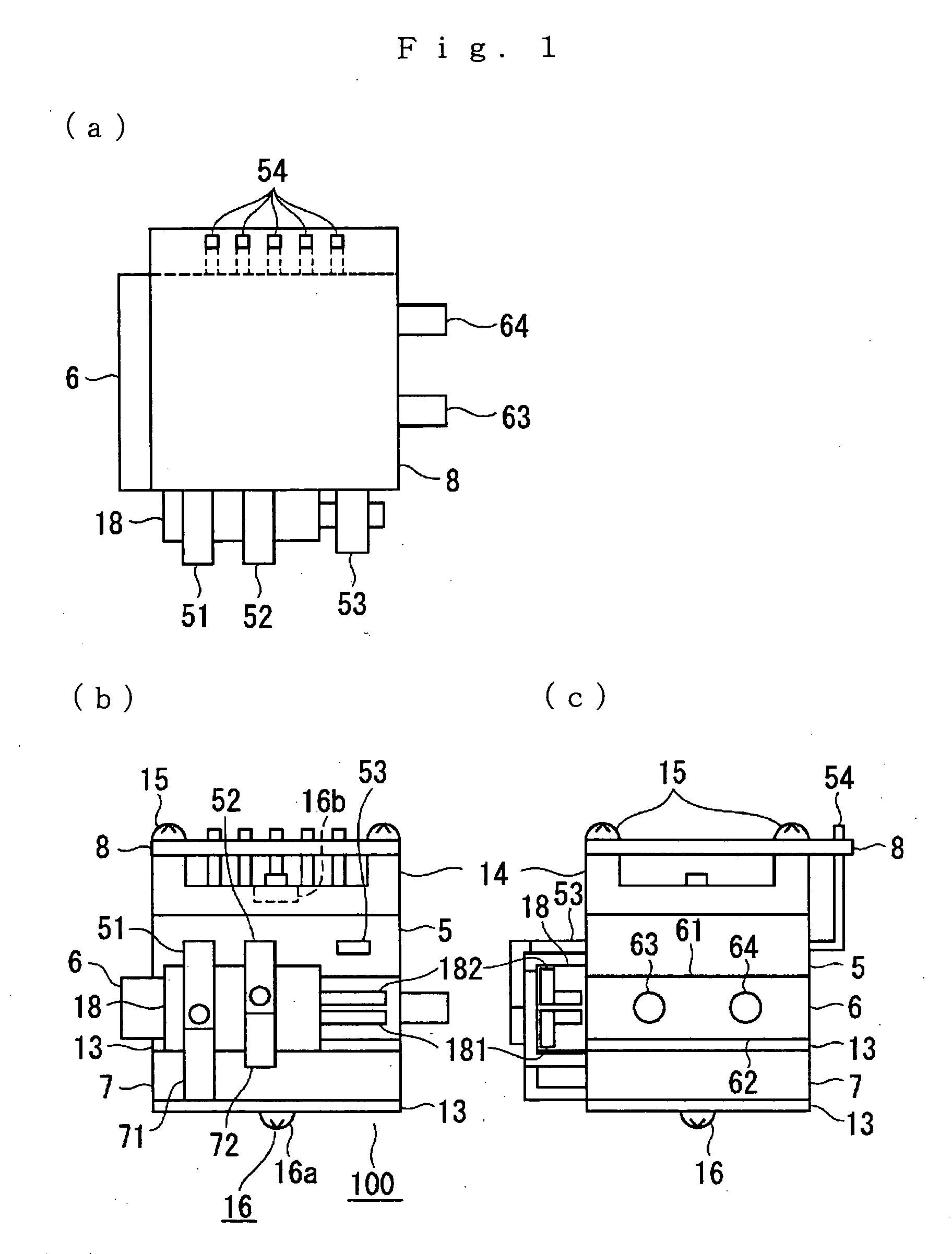
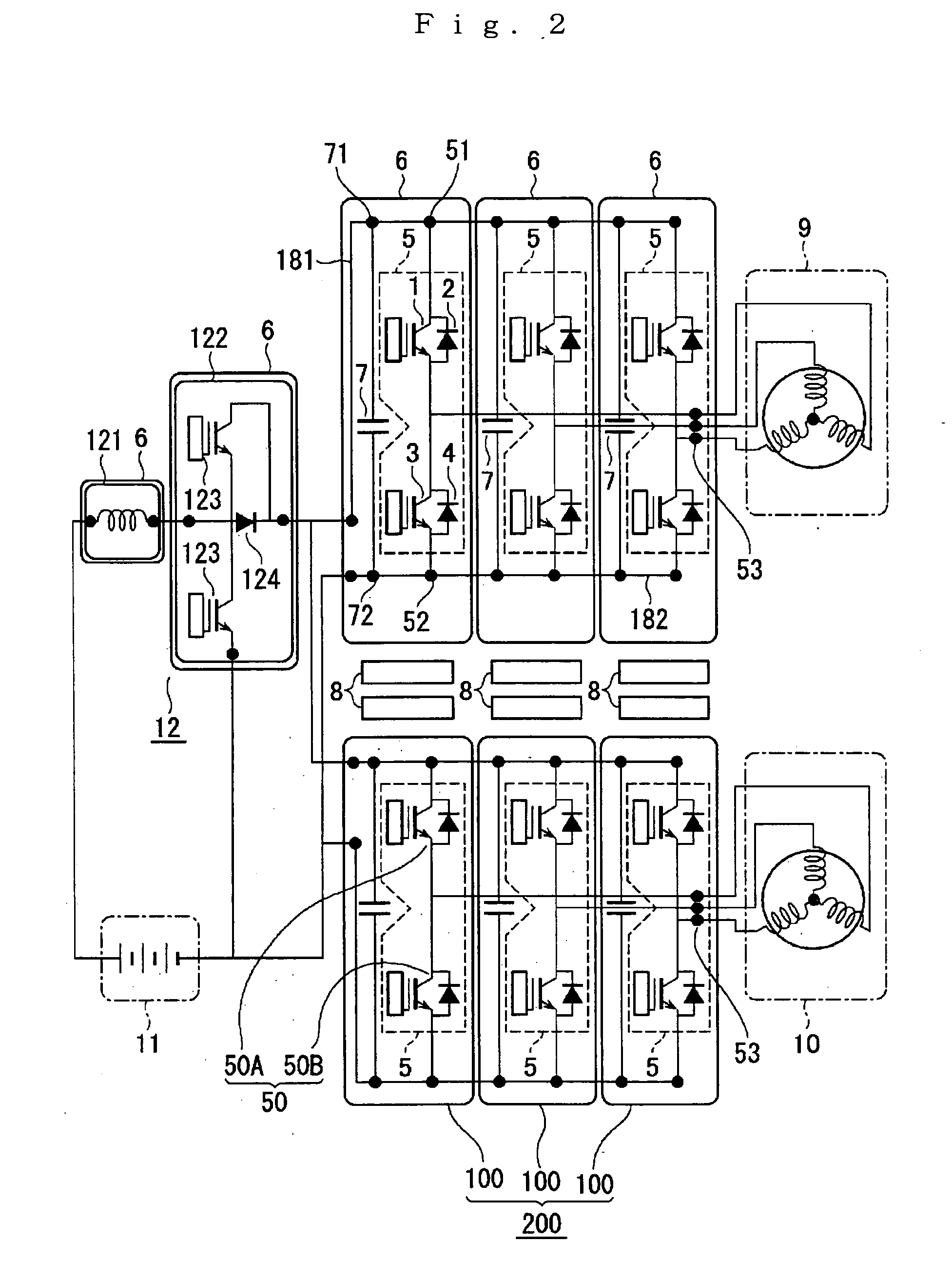
[0015]FIG. 1 shows schematically the exterior of a power unit device according to a first preferred embodiment of the invention, FIG. 1A being a plan view, FIG. 1B a front view and FIG. 1C a side view. FIG. 2 is a schematic system view showing the internal construction of the power unit device shown in FIGS. 1A through 1C and a power converter device constructed to control a 3-phase a.c. rotary electric machine (hereinafter simply called a motor) using six of these power unit devices. The same reference numerals denote the same or equivalent parts throughout the figures.
[0016] In the figures, a power unit device 100 has a heat sink 6 having a first heat-receiving part 61 and formed on the opposite side from that a second heat-receiving part 62; a power module 5, in firm contact with the first heat-receiving part 61, containing a power semiconductor element 50 for performing DC-AC conversion (during power operation) and AC-DC conversion (during regenerative operation) for one phase;...
second preferred embodiment
[0029]FIG. 3 is a construction view showing schematically the main parts of a power converter device according to a second preferred embodiment of the invention. In this second preferred embodiment, three one-phase power unit devices 100 according to the first preferred embodiment shown in FIG. 1 are used to construct a power converter device for drive-controlling one 3-phase motor. In the figure, a power converter device 200 has three power unit devices 100 disposed radially with approximately uniform angular spacing, circular conductors 211, 212 are connected to conducting members (181, 182 in FIG. 1) of the power unit devices 100 by screw fastenings (not shown), and terminal parts 211a, 212a of the conductors 211, 212 are connected to the P pole and the N pole of a power supply battery (not shown).
[0030] Main terminal connection parts (53 of FIG. 1) for conducting power between the power unit devices 100 and the motor side are also connected to circular conductors 213U, 213V, 21...
third preferred embodiment
[0032]FIG. 4 is a construction view showing schematically the main parts of a power converter device according to a third preferred embodiment of the invention. Whereas in the power converter device of the second preferred embodiment described above three of the power unit device shown in FIG. 1 were disposed in a circle with uniform angular spacing, in this third preferred embodiment three are disposed in a straight line. In the figure, the power unit devices 100 are disposed with approximately equal spacing in a straight line, and straight conductors 211, 212 of a P pole and an N pole connected to a power supply battery are connected to the conducting members of the power unit devices 100 (181, 182 in FIG. 1) by screw fastenings (not shown). The main terminal connection parts (53 of FIG. 1) for conducting power to the motor side of the power modules are also integrally embedded in a power conductor member 210 and connected by screw fastenings, and electrically connected to the mot...
PUM
 Abstract
Description
Claims
Application Information