Tunable fiber laser light source
a fiber laser and light source technology, applied in semiconductor lasers, instruments, optical elements, etc., can solve the problems of low light density, inability to detect light signals, low intensity and density of light from light sources with respect to wavelengths, etc., to achieve high deflection velocity, narrow band width, and extend optical path length
- Summary
- Abstract
- Description
- Claims
- Application Information
AI Technical Summary
Benefits of technology
Problems solved by technology
Method used
Image
Examples
first embodiment
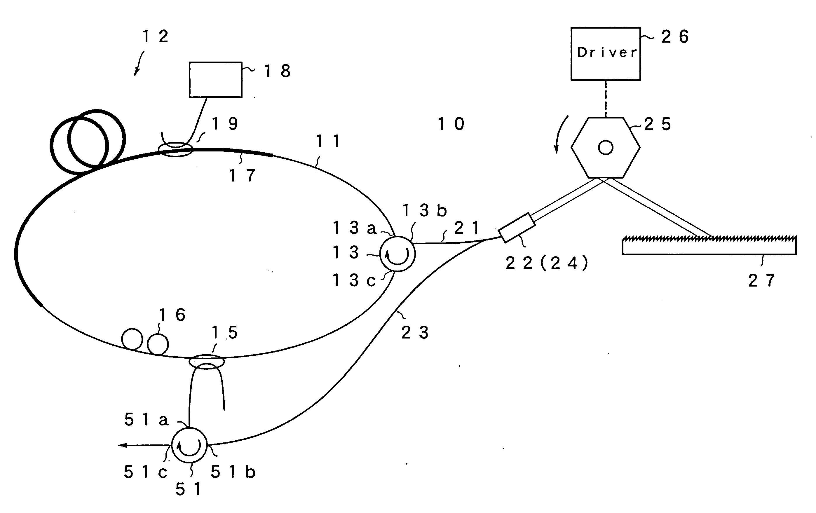
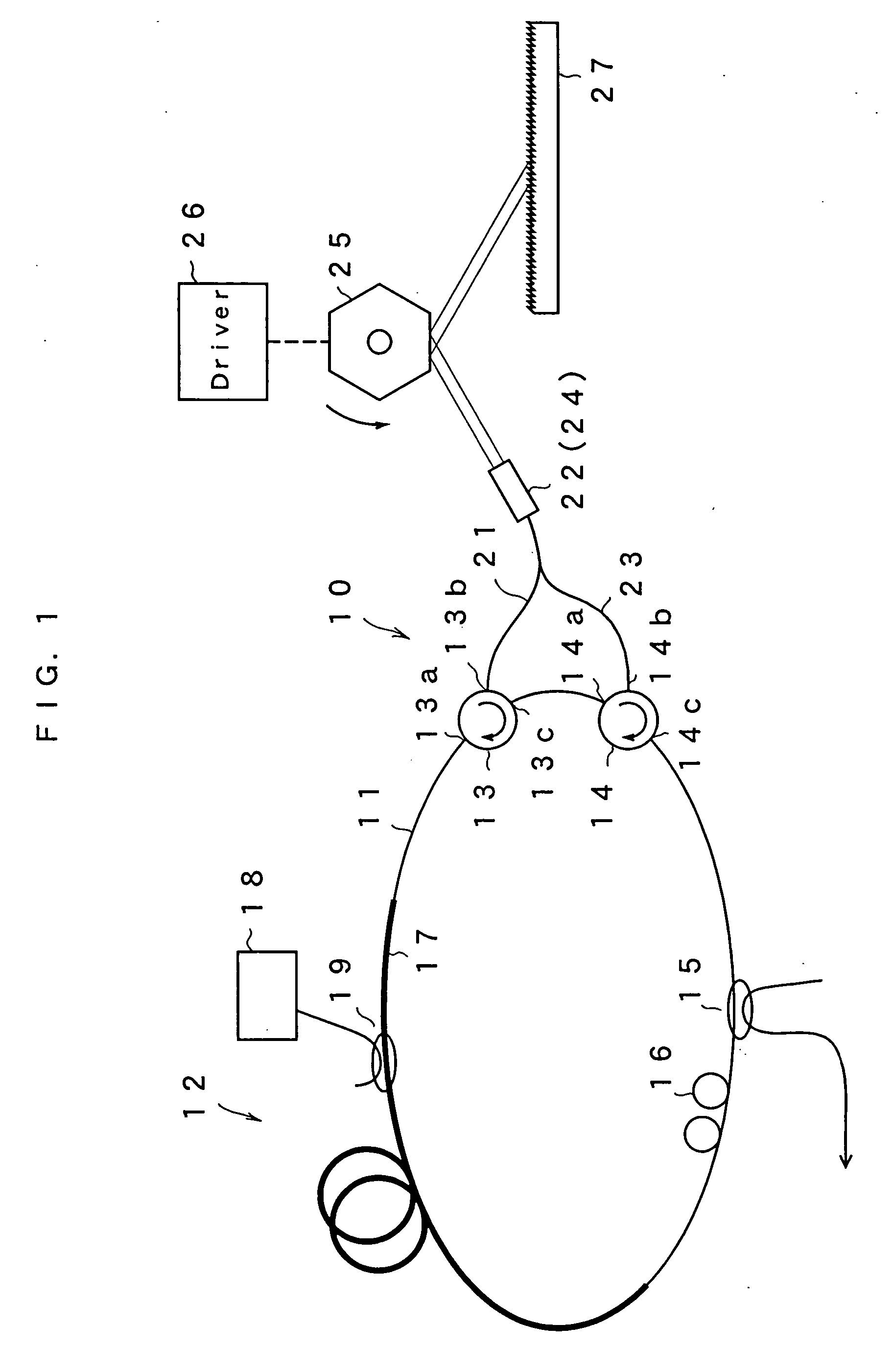
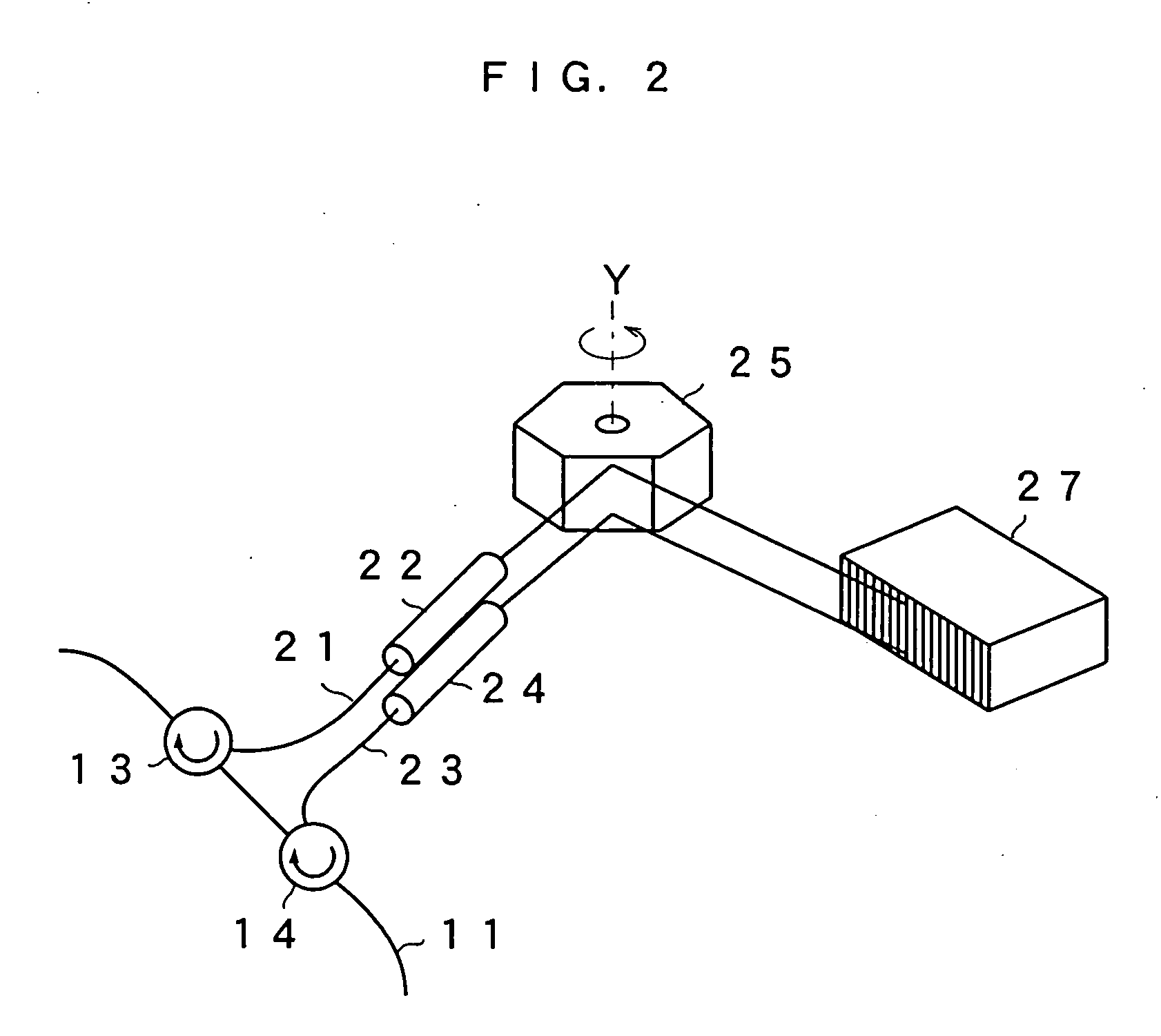
[0046]FIG. 1 is a schematic view showing the configuration of a tunable fiber laser light source according to a first embodiment of the present invention. A tunable fiber laser light source 10 of this embodiment forms a loop by including an optical fiber 11. In a part of the loop, a gain medium 12, optical circulators 13 and 14, an optical coupler 15 and a polarization controller 16 are provided. The gain medium 12 has an erbium doped fiber 17 provided in a part of the optical fiber loop and doped with erbium ions (Er3+), a semiconductor laser 18 for exciting the fiber for emitting pump light to the erbium doped fiber 17, and a WDM coupler 19. The wavelength bandwidth of the gain can be adjusted by selecting a material with which the erbium doped fiber is doped. The optical fiber loop has a length of, for example, 1 to 50 m. The semiconductor laser 18 for exciting has a wavelength of, for example, 1480 nm or 980 nm and amplifies light passing through the erbium doped fiber 17. The o...
second embodiment
[0056] Next, a second embodiment of the present invention will be described. There is no difference between the present embodiment and the first embodiment in terms of the optical fiber loop, and the structure from the circulator 13 to the optical fibers 21 and 22, and collimate lenses 23 and 24. In the present embodiment, an optical beam diameters of the light emitted from the collimate lenses 23 and 24 are expended as shown in FIG. 5. When a beam diameter of an optical beam from the collimate lenses 23 and 24 are W1, the optical beam diameters are enlarged to W2 by a beam expander 31 having a prism shape as shown in FIG. 5. The light reflected in the polygon mirror 25, the optical beam diameters of which are further enlarged to W3 by a beam expander 32, is added to the diffraction grating 27. The optical beam diameters of the incident light with respect to the diffraction grating 27 can be thus enlarged.
[0057]FIG. 6 is an enlarged view of the beam expander 32 and the diffraction ...
third embodiment
[0064]FIG. 9 is a view showing a tunable fiber laser light source according to a third embodiment of the present invention. This embodiment uses a four-port type optical circulator as a light branch incident section in place of two three-port type optical circulators. The four-port type optical circulator 41 has terminals 41a and 41d connected to the optical fiber loop. Light inputted from the terminal 41a is emitted to a terminal 41b of the optical circulator. The light inputted from the terminal 41b is emitted from a terminal 41c. The light inputted from the terminal 41c is emitted from the terminal 41d. The light inputted from the terminal 41d is emitted from the terminal 41a. Consequently, this embodiment can use the four-port type optical circulator 41 as the light branch incident section in place of two optical circulators 13 and 14 of the first embodiment. Other construction is the same as in the first embodiment. In this case, the rotation of the polygon mirror 25 along the ...
PUM
 Abstract
Description
Claims
Application Information
 - R&D
- Intellectual Property
- Life Sciences
- Materials
- Tech Scout
- Unparalleled Data Quality
- Higher Quality Content
- 60% Fewer Hallucinations
Browse by: Latest US Patents, China's latest patents, Technical Efficacy Thesaurus, Application Domain, Technology Topic, Popular Technical Reports.
© 2025 PatSnap. All rights reserved.Legal|Privacy policy|Modern Slavery Act Transparency Statement|Sitemap|About US| Contact US: help@patsnap.com


