
Method for manufacturing hydrorefining catalyst, and metal recovery method

a hydrorefining catalyst and metal recovery technology, applied in the direction of catalyst activation/preparation, metal/metal-oxide/metal-hydroxide catalyst, physical/chemical process catalyst, etc., can solve the problem of reducing the activity of the catalyst obtained by a conventional recycling method, and affecting the mechanical strength of the catalyst. , to achieve the effect of excellent mechanical strength

Inactive Publication Date: 2006-11-16
KOYAMA HIROKI +3
View PDF10 Cites 31 Cited by
  • Summary
  • Abstract
  • Description
  • Claims
  • Application Information

AI Technical Summary

Benefits of technology

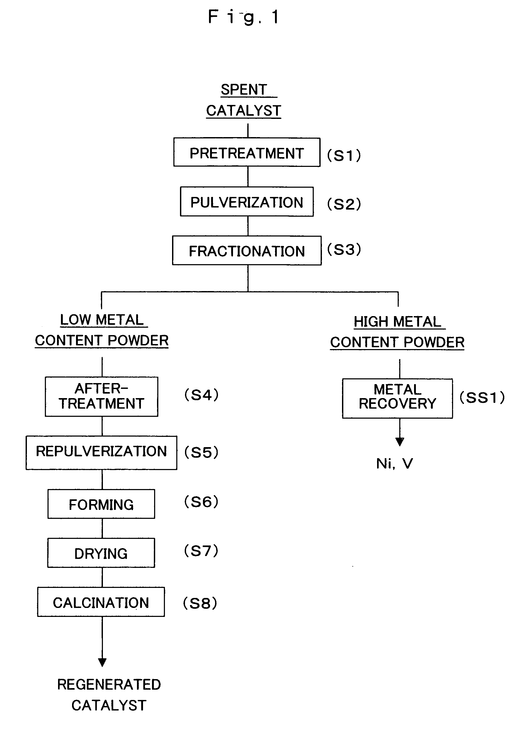
[0013] Furthermore, in the manufacturing method of the present invention, it is preferable if the catalyst powder is adjusted as a volume of pores of the catalyst with a diameter of 50 to 2000 nm, which are macropores that are effective for the diffusion of the metal compounds in the heavy oil into the catalyst interior, is large, such as 0.2 cm3 / g or greater, for example, and the volume of pores with a diameter of 2000 nm or more, which are macropores that lower the mechanical strength, is small, such as 0.1 cm3 / g or less. Accordingly, the regenerated catalyst has a large metal build-up capacity, its activity is decreased less by metal build-up, and the demetalization activity is particularly high. Therefore, a catalyst of relatively high activity can be manufactured from a spent catalyst, and since the catalyst is recycled, the final amount of waste material is reduced.
[0015] A second aspect of the present invention provides a method for recovering metal from a hydrorefining catalyst that has been used in the hydrorefining of a heavy oil, comprising the steps of obtaining a catalyst powder by pulverizing the used hydrorefining catalyst; fractionating the obtained catalyst powder according to the amount of metal contained in the catalyst powder; and recovering the metal component from the fractionated catalyst powder. A high concentration of metal builds up on a spent catalyst used in hydrorefining, and particularly on the outer surface of the spent catalyst. This metal can be recovered from the catalyst on which the metal component is deposited at a high yield by pulverizing the catalyst and then fractionating out the catalyst powder with a high metal content. In actual practice, iron is deposited on the outermost surface of a spent catalyst. In view of this, if the spent catalyst is pulverized into a powder, and the portion of the powder containing a larger amount of iron (which interacts strongly with a magnetic field) is sorted out, this powder will at the same time contain large amounts of vanadium and nickel. Therefore, by subjecting a pulverized spent catalyst powder to magnetic separation and sorting out the powder containing iron, it is possible to obtain the portion of the spent catalyst containing more vanadium and nickel, which affords higher metal recovery efficiency.
[0017] The hydrogenation active metal of the hydrorefining catalyst of the present invention can include at least one of molybdenum and tungsten, and at least one of nickel and cobalt. This allows a regenerated catalyst with excellent mechanical strength to be obtained.

Problems solved by technology

This degradation is particularly pronounced when the hydrocarbon oil is a heavy oil.
Still, the activity of a catalyst obtained by a conventional recycling method is not as high as that of a new catalyst.
Also, the mechanical strength is diminished by treatments such as calcination performed in order to remove the coke.
This decrease in mechanical strength is a problem in that the catalyst breaks up into a powder when repacked into the reactor.
Consequently, the reuse of such catalysts has been limited.

Method used


Image

  • Method for manufacturing hydrorefining catalyst, and metal recovery method
  • Method for manufacturing hydrorefining catalyst, and metal recovery method

Examples


examples

[0049] The present invention will now be described through examples, but the present invention should not be construed as being limited by these examples.

Desulfurization Catalyst

[0050] Pseudo-boehmite powder was kneaded and formed into the form of cylinders ( 1 / 12 inch) and quadrilobe columns ( 1 / 22 inch). These were each calcined for 1 hour at 600° C. to produce γ-alumina carriers, which were impregnated in an ammonium molybdate aqueous solution and a nickel nitrate aqueous solution, respectively, and then dried for 20 hours at 130° C., after which these products were calcined for 0.5 hour at 450° C. to obtain two types of desulfurization catalyst of different shapes. Table 1 lists the composition and properties of the resulting desulfurization catalyst comprising 1 / 12-inch cylinders (hereinafter referred to as the cylindrical desulfurization catalyst) and the desulfurization catalyst comprising 1 / 22-inch quadrilobe columns (hereinafter referred to as the quadrilobe desulfurizat...


PUM

PropertyMeasurementUnit
Nanoscale particle sizeaaaaaaaaaa
Specific volumeaaaaaaaaaa

Abstract

A heavy oil is hydrorefined using a hydrorefining catalyst. A spent hydrorefining catalyst whose activity has decreased is heat treated (S1) and pulverized to obtained a regenerated powder (S2). This regenerated powder is fractionated according to its metal content (S3), formed (S6), dried (S7), and calcined (S7) to manufacture a regenerated catalyst whose volume of pores with a diameter of 50 to 2000 nm is at least 0.2 ml / g, and whose volume of pores with a diameter over 2000 nm is no more than 0.1 mL / g. Using this regenerated catalyst, a heavy oil containing at least 45 wt ppm vanadium and nickel as combined metal elements is hydrodemetalized, and the vanadium and nickel are recovered from the used regenerated catalyst (SS1). Through hydrorefining, the metal components are recovered more efficiently, and the spent catalyst can be reused to manufacture a regenerated catalyst that exhibits high reaction activity.

Description

CROSS-REFERENCE [0001] This application is a Divisional Application of U.S. application Ser. No. 10 / 310,903 filed on Dec. 6, 2002, which is a Continuation Application of International Application No. PCT / JP01 / 04802 which was filed on Jun. 7, 2001 claiming the conventional priority of Japanese patent Applications No. 2000-171427 filed on Jun. 8, 2000 and No. 2000-218139 filed on Jul. 19, 2000.BACKGROUND OF THE INVENTION [0002] 1. Field of the Invention [0003] This invention relates to a method for manufacturing a regenerated catalyst using a spent catalyst that has been used in the hydrorefining of a petroleum distillate and for reusing the regenerated catalyst. It also relates to a method with which the vanadium and other metals contained in a heavy oil are recovered by hydrorefining. [0004] 2. Description of the Related Art [0005] A hydrorefining catalyst is generally manufactured by supporting molybdenum and other such hydrogenation active metal components on a porous carrier such...

Claims


Application Information

Patent Timeline
IPC IPC(8): B01J23/00B01J23/85B01J23/887B01J23/94B01J35/02B01J35/10B01J37/00C10G45/04C10G45/08C22B7/00C22B34/22
CPCB01J23/85B01J23/8877B01J23/94B01J35/023B01J35/10B01J35/108C22B34/225B01J37/0036C10G45/04C10G45/08C22B7/009C22B34/22B01J37/0009Y02P10/20B01J35/60B01J35/40B01J35/66
Inventor KOYAMA, HIROKISAITO, TORUIWATA, YOSHIKINAKAOKA, CHIKANORI
Owner KOYAMA HIROKI
Learn More