

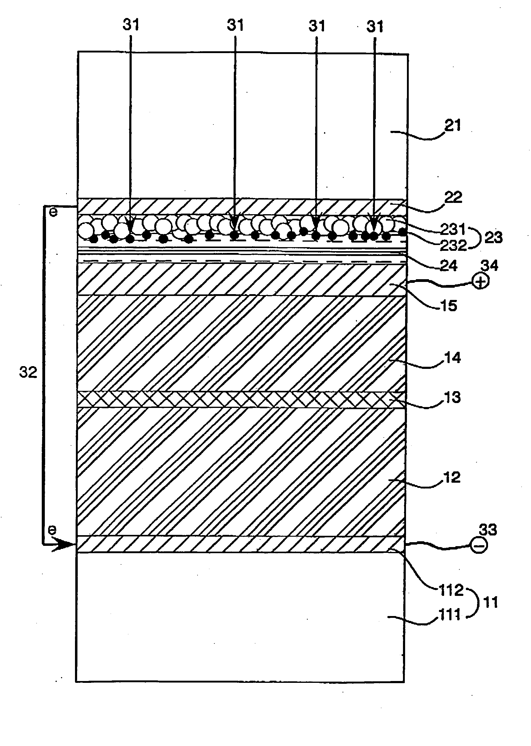
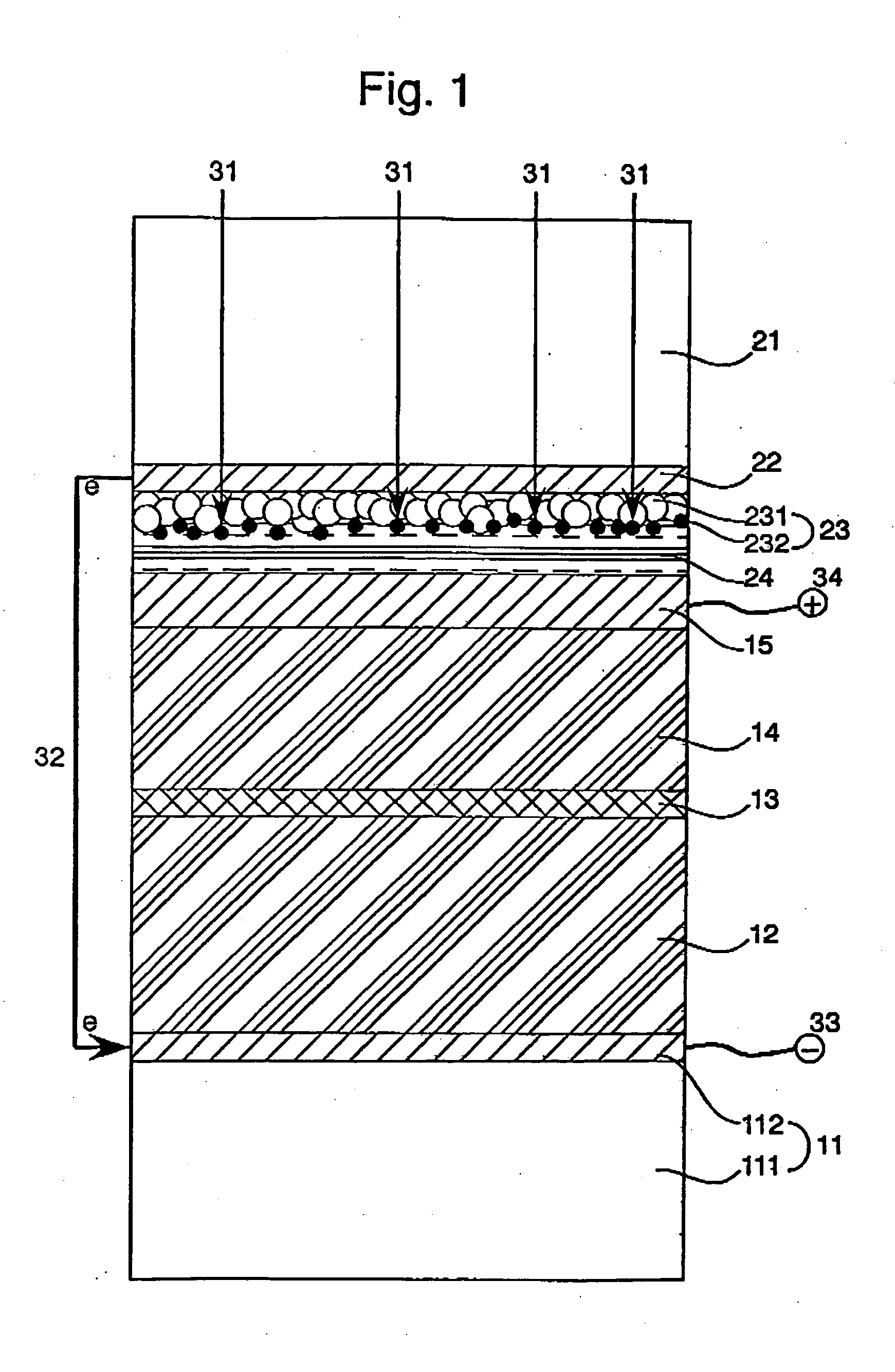
Photochargeable layered capacitor comprising photovoltaic electrode unit and layered capacitor unit
a photovoltaic electrode and capacitor technology, applied in capacitor collector combinations, electrolytic capacitors, electrochemical generators, etc., can solve the problems of high charging efficiency and insufficient discharging efficiency of capacitors, and achieve high efficiency, simple structure, and high efficiency
- Summary
- Abstract
- Description
- Claims
- Application Information
AI Technical Summary
Benefits of technology
Problems solved by technology
Method used
Image

Examples
example 1
(Preparation of Outer Counter-Electrode Layer)
[0084] One surface of a polyethylene naphthalate (PEN) film (thickness: 200 μm) was covered with aluminum membrane (thickness: 500 nm) to prepare an outer counter-electrode layer.
(Formation of Outer Storage Material Layer)
[0085] 9 weight parts of porous active carbon (active carbon fiber) having specific surface area of 1,100 m2 / g (measured according to BET method) and average primary particle size of 0.03 μm, 1 weight part of acetylene black and 1 weight part of N-methylpyrrolidone solution of polyvinylidene fluoride (binder) were mixed to form a paste. The aluminum surface of the outer counter-electrode layer was coated with the paste, dried at 60° C., and mechanically pressed to cover the aluminum surface with a carbonaceous layer containing active carbon (thickness: about 200 μm, coated amount of carbon: 2.5 mg / cm2). The formed film was further heated at 150° C. in the dry air for 10 minutes.
(Preparation of Inner Counter-Elect...
example 2
(Preparation of Outer Counter-Electrode Layer)
[0097] A metallic titanium sheet (thickness: 50 μm) was used as an outer counter-electrode layer.
(Formation of Outer Storage Material Layer)
[0098] The outer storage material layer was formed on the outer counter-electrode layer in the same manner as in the Example 1.
(Preparation of Inner Counter-Electrode Layer)
[0099] Surfaces of a titanium sheet (thickness; 50 μm) were covered with platinum membrane (thickness: 20 nm) to prepare an inner counter-electrode layer.
(Formation of Inner Storage Material Layer)
[0100] 1 weight part of ruthenium dioxide (average particle size: 18 μm), 2 weight parts of tin dioxide (average particle size: 60 nm) and 2 weight parts of nickel oxide (average particle size: 8 μm) were mixed to prepare active material powder. The active material powder was ground in an agate mortar. 10 weight parts of the powder was mixed with 1 weight part of an N-methylpyrrolidone solution of polyvinylidene fluoride (bind...
example 3
(Preparation of Outer Counter-Electrode Layer)
[0108] A metallic titanium sheet (thickness: 50 μm) was used as an outer counter-electrode layer.
(Formation of Outer Storage Material Layer)
[0109] A conductive polypyrrole was prepared according to an electrolytic polymerization method. 1 weight part of the conductive polypyrrole was mixed with 1 weight part of the active carbon prepared in Example 1. 10 weight parts of the mixture was dispersed in 1 weight part of N-methylpyrrolidone solution of polyvinylidene fluoride (binder) to form a paste. One surface of the inner counter-electrode layer (titanium sheet) was coated with the paste, heated at 100° C. in the air for 10 minutes to cover the surface with a storage layer comprising a carbonaceous material and an electrodically active material (thickness: about 200 μm, coated amount of polypyrrole: 1.0 mg / cm2)
(Preparation of Inner Counter-Electrode Layer)
[0110] Surfaces of a titanium sheet (thickness: 50 μm) were covered with plat...
PUM
 Abstract
Description
Claims
Application Information