This helps you quickly interpret patents by identifying the three key elements:
Problems solved by technology
Method used
Benefits of technology
[0022] According to the present invention, the silica fine particles have fine voids in the exterior and interior parts thereof, and the voids are filled with gas, for example, air having a refractive index of 1. Therefore, the refractive index of the silica fine particles per se is low and, even when the silica fine particles are homogenously dispersed without the formation of any aggregate in the coating film, the refractive index of the coating film can be lowered. Specifically, the refractive index of the void-containing silica fine particles has a lower refractive index of 1.20 to 1.45 which is lower than conventional silica fine particles free from gas in the interior thereof (refractive index n=about 1.46), and, thus, the refractive index of the coating film can be brought to not more than 1.45, preferably not more than 1.40. Further, since voids are protected by an outer shell of fine particles, the formed coating film is compacted by the aggregative force and hardness of the fine particles dispersed in the cured resin composition, contributing to improved mechanical strength of the coating film.
[0023] These fine particles are slightly aggregated in the coating film, and, consequently, concaves and convexes having a fineness approximately below the wavelength of the visible light are formed particularly on the outermost surface of the coating film. As a result, a nanoporous structure is formed within or on the surface of the coating film, and, thus, a structure into
Problems solved by technology
Further, the gas phase method involves a problem that, since a special heating device or ion generating accelerator is used, the production apparatus is complicated, and, thus, the size of the production apparatus is so large that the production cost is necessarily increased.
In addition, in the gas phase method, it is difficult to form a large-area transparent thin film or to evenly form a transparent thin film on the surface of a film or the like having a complicated shape.
On the other hand, the formation of the low refractive index layer by spraying, i.e., one of the coating methods, is disadvantageous, for example, in that the utilization efficiency of the coating liquid is low and the regulation of film formation conditions is difficult.
The formation of the low refractive index layer by roll coating, gravure coating, slide coating, dip coating, screen printing or the like can realize good utilization efficiency of the film forming material and thus is excellent in mass production and equipment cost, but on the other hand, in general, it involves a problem that the transparent thin film formed by the coating method is inferior to that formed by the gas phase method in function and quality.
However,
Method used
Image
Click on the blue label to locate the original text in one second.
Reading with bidirectional positioning of images and text.
Examples
example 1
[0180] Preparation of composition for low refractive index layer formation
[0181] The following ingredients were mixed together according to the following formulation to prepare a composition for low refractive index layer formation.
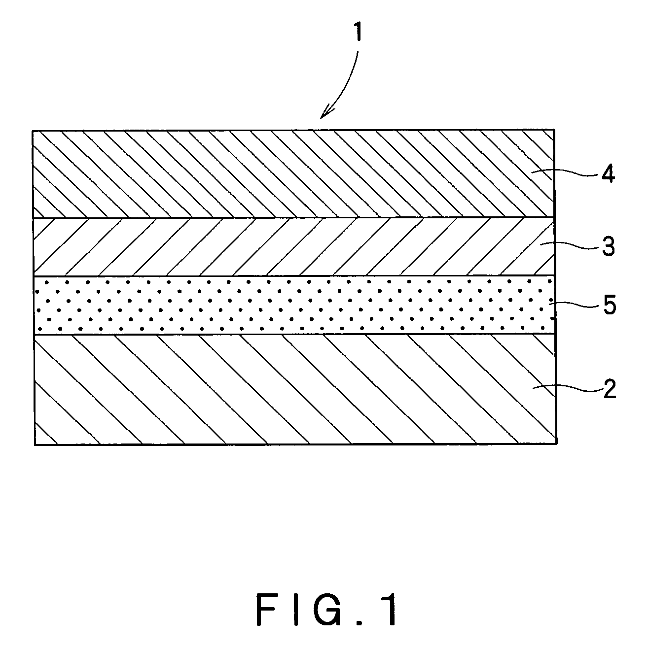
[0183] Preparation of base material / hardcoat layer / low refr...
example 2
[0186] A hardcoat layer and a low refractive index layer were formed in the same manner as in Example 1, except that the composition for low refractive index layer formation used in Example 1 was changed as follows. Thus, a laminate of Example 2 was prepared.
[0187] A hardcoat layer and a low refractive index layer were formed in the same manner as in Example 1, except that the composition for low refractive index layer formation used in Example 1 was changed as follows. Thus, a laminate of Example 3 was prepared.
PUM
Property
Measurement
Unit
Fraction
aaaaa
aaaaa
Fraction
aaaaa
aaaaa
Percent by mass
aaaaa
aaaaa
Abstract
There is provided an antireflective laminate having a low refractive index and excellent mechanical strength, which comprises a coating layer of an ionizing radiation curing-type resin composition comprising ionizing radiation curing group-containing hollow silica fine particles. The antireflective laminate comprises a light transparent base material and at least a low refractive index layer having a refractive index of not more than 1.45 provided on the light transparent base material, wherein the low refractive index layer comprises an ionizing radiation curing-type resin composition and silica fine particles having an outer shell layer with the interior of the silica fine particles being porous or void, and, for a part or all of the silica fine particles, at least a part of the surface of the silica fine particle has been treated with an ionizing radiation curing group-containing silane coupling agent.
Description
TECHNICAL FIELD [0001] The present invention relates to an antireflective or antireflection laminate having a low refractive index and excellent mechanical strength, which comprises a coating layer of an ionizing radiation curing-type resin composition comprising ionizing radiation curing group-containing hollow silica fine particles. BACKGROUND ART [0002] Display surfaces in image display devices such as liquid crystal displays (LCDs) or cathode ray tube display devices (CRTs) are required to cause no significant reflection of light applied from external light sources such as fluorescent lamps from the viewpoint of enhancing the visibility of the image. [0003] The phenomenon that the reflectance is reduced by coating a low refractive index transparent film onto the surface of a transparent object has hitherto been known. The visibility can be improved by providing an antireflection film utilizing this phenomenon onto the display surface of an image display device. Antireflection fi...
Claims
Application Information
Patent Timeline
Application Date:The date an application was filed.
Publication Date:The date a patent or application was officially published.
First Publication Date:The earliest publication date of a patent with the same application number.
Issue Date:Publication date of the patent grant document.
PCT Entry Date:The Entry date of PCT National Phase.
Estimated Expiry Date:The statutory expiry date of a patent right according to the Patent Law, and it is the longest term of protection that the patent right can achieve without the termination of the patent right due to other reasons(Term extension factor has been taken into account ).
Invalid Date:Actual expiry date is based on effective date or publication date of legal transaction data of invalid patent.