
Process for the production of niobium oxide powder for use in capacitors

a technology of niobium oxide and niobium monoxide, which is applied in the direction of niobium compounds, inorganic chemistry, electrolytic capacitors, etc., can solve the problems of niobium monoxide, niobium monoxide, and more than one type of niobium oxide, so as to improve the chemical, physical and morphological properties of the product, improve the control of each reducing step, and improve the effect of quality

Inactive Publication Date: 2006-12-07
CIA BRASILEIRA DE METALURGIA E MINERCAO +1
View PDF4 Cites 9 Cited by
  • Summary
  • Abstract
  • Description
  • Claims
  • Application Information

AI Technical Summary

Benefits of technology

[0003] The reduction of the niobium pentoxide (Nb2O5) to niobium monoxide (NbO) in two steps allows a better control of each reducing step, allowing the use of the most convenient raw materials and the use of the most adequate equipment for each step of the process, thus lowering the production costs. And most importantly, this process allows a better control of the chemical, physical and morphological properties of the product obtained thereby.
[0005] Following this course, the niobium monoxide (NbO) may be reduced in a controlled manner, yielding a powder of high purity, porous, with controlled morphology, with low apparent density and large specific surface area.

Problems solved by technology

However, the main problem of the partial reducing of niobium oxides in one sole step is the difficulty to obtain a product having only niobium monoxide in its composition, as may be noted in the above cited patents.
The existence of more than one type of niobium oxide or even of residual metallic niobium, in addition to the niobium monoxide, is deleterious for the use thereof in capacitors.
Furthermore, the final morphology that is obtained is difficult to control and it is not usually the most adequate for the manufacture of high performance capacitors (high capacitance and low current leakage).

Method used


Image

  • Process for the production of niobium oxide powder for use in capacitors
  • Process for the production of niobium oxide powder for use in capacitors

Examples


example 1

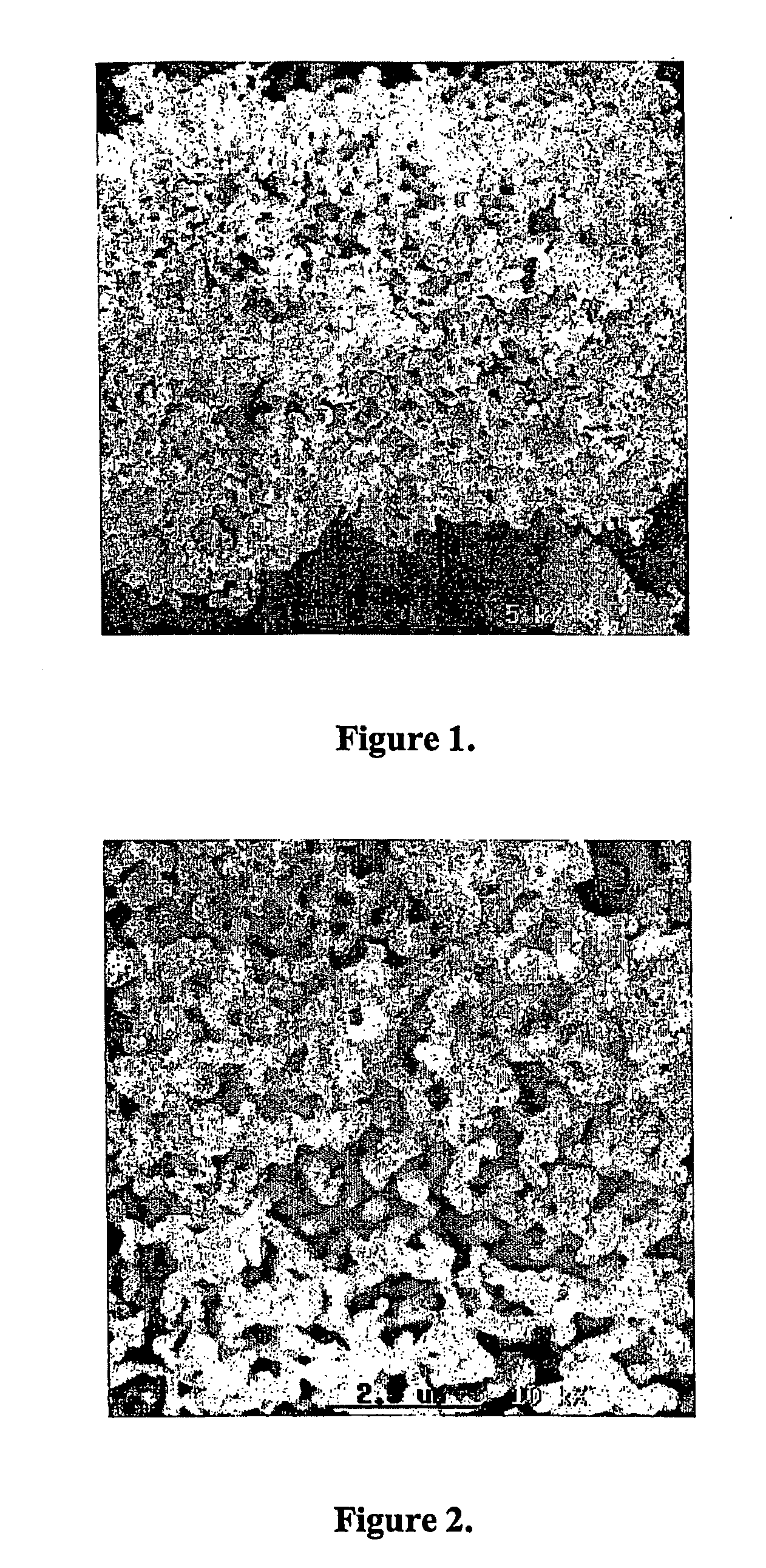
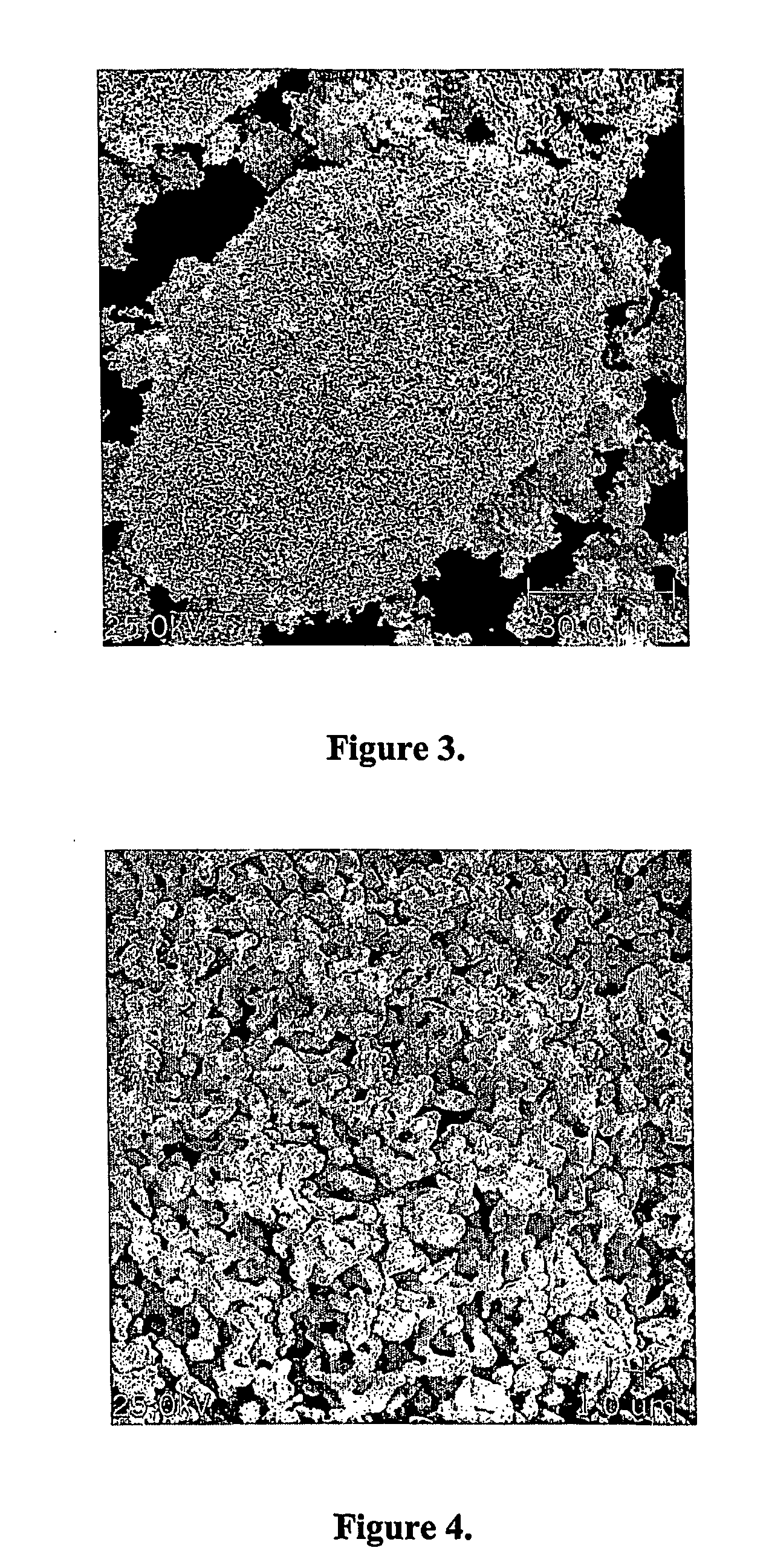
[0032] First reduction step: 200 grams of powdered niobium pentoxide were loaded into a tubular furnace. Hydrogen gas was admitted to the furnace chamber, and the furnace temperature was raised from ambient temperature to 800° C. The load was kept at this temperature for 300 minutes, whereupon the heating was turned off. The hydrogen atmosphere was maintained until the load reached ambient temperature, whereupon the furnace chamber was pressurized with nitrogen prior to removal of the load from the furnace. The product of this first reaction step had the following properties:

[0033] X-Ray Diffraction: NbO2

[0034] Specific surface area, BET analysis method: 3.2 m2 / g

[0035] Porosity: 83.8%

[0036] Second reduction step: 6 grams of niobium dioxide, produced in the first reduction step, were loaded into a niobium crucible, together with 34 g of powdered niobium hydride with particle size of less than 0.6 mm and greater than 0.3 mm. The crucible containing the mixture was loaded into the ...

example 2

[0042] First reduction step: 250 grams of powdered niobium pentoxide were loaded into a tubular furnace. Hydrogen gas was admitted to the furnace chamber, and the furnace temperature was raised from ambient temperature to 800° C. The load was kept at this temperature for 150 minutes, whereupon the heating was turned off. The hydrogen atmosphere was maintained until the load reached ambient temperature, whereupon the furnace chamber was pressurized with nitrogen prior to removal of the load from the furnace. The product of this first reaction step had the following properties:

[0043] X-Ray Diffraction: NbO2

[0044] Specific surface area, BET analysis method: 3.5 m2 / g

[0045] Porosity: 84.4%

[0046] Second reduction step: 180 grams of niobium dioxide, produced in the first reduction step, were loaded into a niobium crucible, together with 1000 g of powdered niobium hydride with particle size of less than 0.6 mm and greater than 0.3 mm. The crucible containing the mixture was loaded into ...

example 3

[0052] First reduction step: 1000 grams of powdered niobium pentoxide were loaded into a tubular furnace. Hydrogen gas was admitted to the furnace chamber, and the furnace temperature was raised from ambient temperature to 800° C. The load was kept at this temperature for 90 minutes, whereupon the heating was turned off. The hydrogen atmosphere was maintained until the load reached ambient temperature, whereupon the furnace chamber was pressurized with nitrogen prior to removal of the load from the furnace. The product of this first reaction step had the following properties:

[0053] X-Ray Diffraction: NbO2

[0054] Specific surface area, BET analysis method: 7.0 m2 / g

[0055] Porosity: 80.4%

[0056] Second reduction step: 890 grams of niobium dioxide, produced in the first reduction step, were loaded into a niobium crucible, together with 5000 g of powdered niobium hydride with particle size of less than 0.6 mm and greater than 0.3 mm. The crucible containing the mixture was loaded into ...


PUM


Abstract

The present invention is related to a process for the production of a powder of niobium monoxide (NbO) having a high purity, large specific surface area, controlled oxygen and nitrogen contents and a morphology adequate for use in the manufacture of capacitors, characterized by comprising two niobium pentoxide (Nb2O5) reduction steps, the first step comprising reducing, by hydrogen, the niobium pentoxide (Nb2O5) to niobium dioxide (NbO2), and the second step comprising reducing niobium dioxide (NbO2) to niobium monoxide (NbO), by using an oxygen getter material in a convenient atmosphere which permits the transfer of the oxygen atoms from the niobium oxide (NbO2) to the getter material, under adequate conditions of time and temperature to form the niobium monoxide (NbO). The particles of powder of niobium monoxide (NbO) produced using the instant process are small, have a large surface area and an appropriate morphology, and are adequate for the production of capacitors.

Description

BRIEF DESCRIPTION OF THE INVENTION [0001] The present invention is related to a process for the production of niobium monoxide (NbO) powder characterized by two niobium pentoxide (Nb2O5) reduction steps, the first step comprising reducing, by hydrogen, of the niobium pentoxide (Nb2O5) to niobium dioxide (NbO2), and the second step comprising reducing the niobium dioxide (NbO2) to niobium monoxide (NbO), by using an oxygen getter material and in a convenient atmosphere allowing the transfer of the oxygen atoms from the niobium dioxide (NbO2) to the getter material, under adequate conditions of time and temperature to form the niobium monoxide (NbO). [0002] The partial reduction of niobium oxides, in one sole step, using refractory or reactive metals and / or hydrides of refractory or reactive metals as oxygen getter materials and in an atmosphere which allows the transfer of oxygen atoms is known in the art, as may be noted in patents Nos. U.S. Pat. No. 6,391,275, U.S. Pat. No. 6,416,7...

Claims


Application Information

Patent Timeline
IPC IPC(8): C01G31/02
CPCC01G33/00C01P2004/03H01G9/0525C01P2006/40C01P2006/12
Inventor TAGUSAGAWA, SOLON YASUHIKOONO, ALBERTO AKIKAZUBENEDUCE, FLAVIO NETOFERREIRA, JOAO BATISTA NETO
Owner CIA BRASILEIRA DE METALURGIA E MINERCAO
Learn More